Constructive connector characteristics - Flap doors
Access
Ribbon : Main data > Main data > Element Manager > Connections > Connector
General Information
The constructive connector characteristics describe certain features of the connector. For example, you can modify the position of the connector in the article.
Attributes
| Preview | Characteristic-Name | Values | Explanation |
|
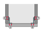
Top mounted flap doors
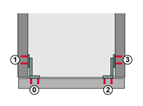
Bottom mounted flap doors
|
Additional part numbers (OPPOSITE_PART_ NUMBERS) |
The characteristic is evaluated for the flap hardware. | |
| Yes | Additionally to the part numbers 0 and 1 the part numbers 2 and 3 are evaluated. The part number 0 is allocated to the flap. The number 1 is allocated to the panel. The part numbers 2 and 3 can be used to depict the mirrored connector. By doing this, 2 is evaluated like 0 and 3 like 1. | ||
| No | No additional part numbers are evaluated. | ||
|
Inset flap fitting front workings (FLAP_FITTING_FRONT_ INSET_TOP) |
Number (editable) |
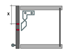
If the front machining (Flap) is offset to the defined value, then this is effective for the top hinged flap fitting. With bottom hinged flaps the machining is offset to the top. The entered part number defines if the connector drawing (DWG) with the front machining or the side machining is offset. There are the variables $H (total height), $HT (height upper door), $HB (height lower door), $TSTHK (Top shelf thickness) and $BSTHK (Bottom shelf thickness). The above-named variables can be combined in the mathematical functions (Tab, min,..). |
|
Inset flap fitting side workings (FLAP_FITTING_SIDE_ INSET_TOP) |
Number (editable) |
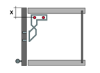
If the side machining (part side) is offset to the defined value, then this is effective for the top hinged flap fitting. With bottom hinged flaps the machining is offset to the top. The entered part number defines if the connector drawing (DWG) with the front machining or the side machining is offset. There are the variables $H (total height), $HT (height upper/top door), $HB (Height lower/bottom door), $HCC (Height center of top/fixed shelf to center of fixed/bottom shelf), $TSTHK (Top shelf thickness) und $BSTHK (Bottom shelf thickness). The above-named Variables can be combined in the mathematical functions (tab(), min(), ...). |
|
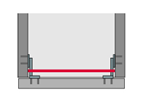
Anchor for SPP (SPP_ANCHOR) |
1 = Yes 0 = No |
If the value is equal 1 , a SPP is generated between the left and right insertion point of the flap connector. To be able to use this characteristic the characteristic Locksystem DWG (SECTION_DWG) or name of the cross-section geometry principle (SECTION) must be defined. |
|
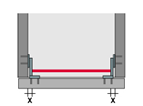
Shortening of SPP (SPP_SUB) |
Number (editable) |
The generated SPP will be shorted for the inserted value. This characteristic only makes sense if also the characteristic Anchor for SPP has been defined. |
|
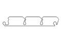
Name of the cross-section geometry principle (SECTION) |
Cross-section geometry principle |
In this feature the name of the cross-sectional geometry of the imos database is stored. The cross-sectional geometries can be created with the help of the Contours Wizards and edited with the Element Manager. |

|
Add distance mounting plate (ADD_DIST_MOUNTING_PLATE) |
Yes No |
The characteristic is evaluated for the flap hardware. Yes = Connector of the flaps is also offset by the distance (characteristic DIST_X) of the mounting plate. The peculiarity is that the mounting plate is sought in another connection to the flap. If no mounting plate is found or No , then the additional offset is 0. Note : Exchange only the connector set of the mounting plate via the Manager / Connection Scan, then the flap fitting doesn’t fit automatically. Only when the flap fitting is inserted again, the new distance of the mounting plate is evaluated. |