
Dimensioning floor plans and elevation views
Dimensioning has been redesigned in iX CAD and PLAN. It allows the imos administrator to individually compile dimensioning principles for every use case – from a work surface plan to full dimensions. For this, the old dimensioning principle has been split into the principles Part-, Floor Plan- and Elevation Dimensioning; the Part Dimensioning is identical with the original Dimensioning principle.
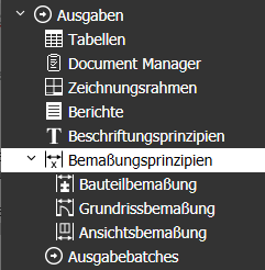
The principles Floor Plan and Elevation Dimensioning can be applied with the corresponding method View Dimensioning in both iX CAD and PLAN. When dimensioning, the program reacts to the present view and room situation. It…
- dimensions articles that are completely or partially visible (to dimension concealed articles simply activate the option Article Contours in the section options),
- minds the visibility of fittings and handles,
- distinguishes articles from one another that are positioned in a different depth,
- dimensions articles that are visible and perpendicular to the viewer in an elevation view,
- identifies room dividers such as kitchen islands to optimize the dimensioning for this use case
Hinweis: The dimensioning in iX2019 SR2 requires principles for Floor Plan and Elevation View Dimensioning. If you update an existing iX 2019 installation to SR2, please download the sample principles predefined by imos. Import the ZIP file in the iX Organizer via Integration>Import. The principles are also available in a DCO package (Design Catalog Online).
Furthermore, download the current imos.dwt which contains relevant dimensioning and text styles. Either add all missing styles in your existing imos.DWT using the AutoCAD® Designcenter (Befehl: ADCENTER) or replace your existing imos.DWT – make a backup of the file before replacing (read the Whitepaper for more information).
The dimensions can be found in the separate layers “imosSectGround.<Number>.AutoDims” and “imosSectView.<Number>.AutoDims”, with consecutive numbering in each case.
The following pages illustrate how an imos data administrator can create his own principles for Floor Plan and Elevation Dimensioning.
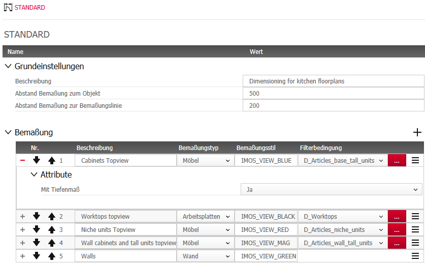
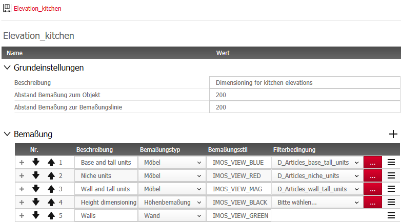
First, define
- the offset between a dimensioning line and an object (view),
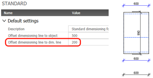
- the offset between two dimensioning lines and
- whether the distance between dimensioning lines should be the height on paper.
in the section Default Settings so that the dimensioning lines do not overlap each other.
In the following section, add as many Dimensioning definitions as you require using the + symbol. A Dimensioning is made up of:
|
Option |
Description |
|
Description |
Free text for entering a unique description |
|
Dimension type |
Choose a dimension type that best fits the use case; depending on the type you select, there are other attributes available as the process continues (see Dimension types Fehler! Verweisquelle konnte nicht gefunden werden.). |
|
Dimension style |
Define a dimension style contained within your IMOS.DWT*. |
|
Filter Condition |
With help from conditions, filter for all articles to which the dimension is to be applied. |
|
Attributes |
Here you will see additional options, dependent of the selected dimension type, e.g., you can activate cutout dimensions for work surfaces. |
Dimension types
Dimension types optimize dimensions for different use cases. The list of choices is different for Floor Plan and Elevation Dimensioning:
Floor plan dimensioning
|
Dimension type |
Description |
Type specific attributes |
|
Furniture |
Dimensions article width |
- Depth dimensions |
|
Work surfaces |
Dimensions work surfaces; excludes distracting offset gaps |
- Depth dimensions - Dimension cutout, e.g. for a sink |
|
Wall |
Dimensions walls; dimensions wall thickness only for free-standing walls |
|
|
Installation |
Dimensions gas/electricity/water connections |
Elevation view dimensioning
|
Dimension type |
Description |
Type specific attributes |
|
Furniture |
Dimensions article width |
- Position of width dimensions (top/ bottom) |
|
Height Dimensioning |
Dimensions article height |
- Separate worktop height dimensions |
|
Wall |
Dimensions walls; dimensions wall thickness only for free-standing walls |
- Position of width dimensions (top/ bottom) |
|
Installation |
Dimensions gas/electricity/water connections |
Example: Elevation View Dimensioning incl. separate worktop height dimension
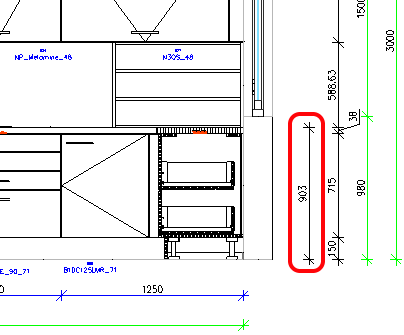
Hinweis: To dimension work surfaces correctly they must be created with iX 2019 SR2.
Dimensioning articles placed behind one another
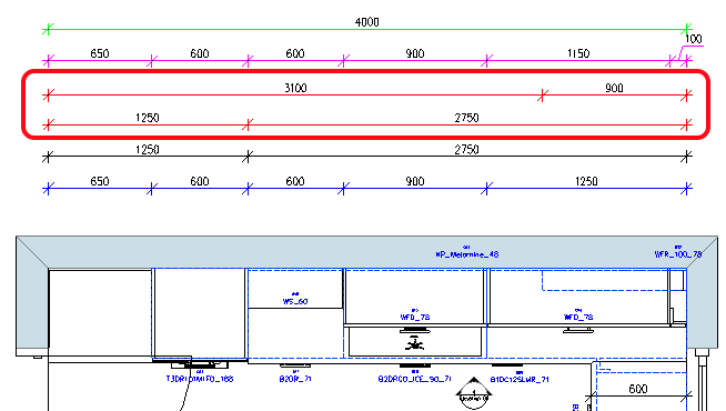
Articles that are placed in different depths and overlapping each other, like the niche shelf (2750 mm) and niche panel (900 mm) shown in the left image, create separate dimension lines for each depth position in the floor plan as well as the elevation view.
Identifying room dividers
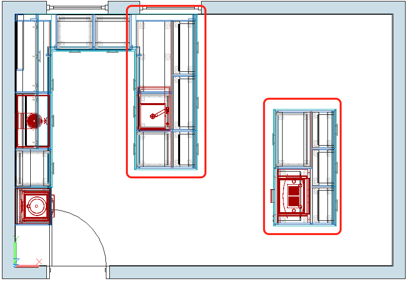
imos identifies rooms dividers. More precisely, it filters articles placed back-to-back to one another. If such a room divider has been identified, different rules apply for the views, dimensions and annotations.
Usually, dimension lines are written behind an article’s rear edge with a distance of „Offset dimensioning line to object“.
However, in a room divider situation, the dimension lines are written in front of the front edge of affected articles. Furthermore, the distance is referenced from „Offset dimensioning line to dimensioning line“. This prevents dimensions inside article contours. Work surfaces on the other hand are still dimensioned at the rear article edge so that they do not overlap with the room divider dimensions.
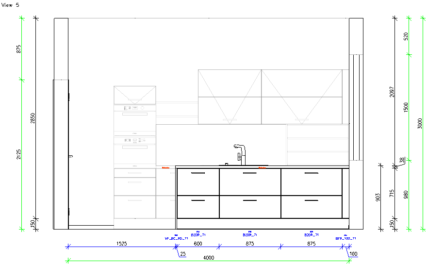
In elevation views, imos identifies room dividers as well and dimensions/ annotates them isolated from its surrounding furniture: only articles located in a depth of 2000 mm behind the section line‘s arrow are dimensioned/ annotated – the remaining objects recede into the background behind a white transparent layer.
Selecting articles via dimension or annotation
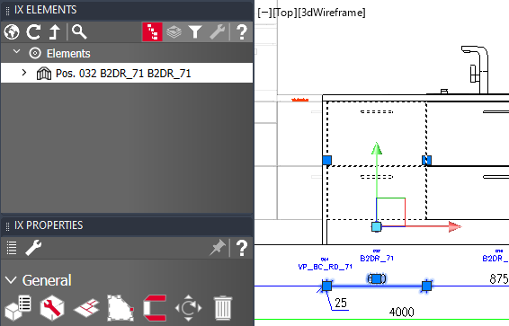
Selecting a dimension or annotation will automatically select the corresponding article in the iXplorer Element palette. Like this you can easily identify what element a dimension/ annotation refers to without second-guessing.
That could also be interesting for you:
- Whitepaper Dimensioning floor plans and elevation views
- Graphic_inch.ini for the USA
- Dimension hidden articles
May 2020 | iX 2019 SR 2
#01271