
Single parts - Side panel
Access
Ribbon : Main data > Main data > Element Manager > Construction Principle > Single Parts
General information
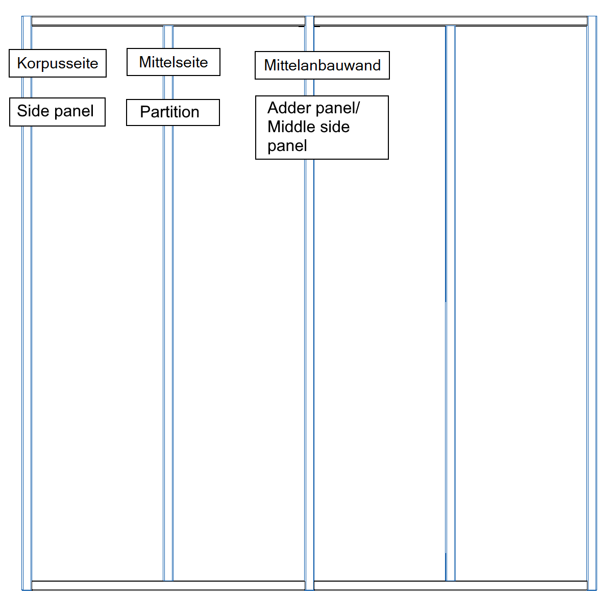
In a 'Side Panel' principle, you can define an adder panel or an outer corpus side.
- Partition:
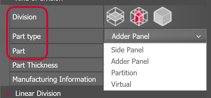
- You define a partition using the 'Single Parts – Partition' principle. In the Article Designer, you can assign this principle to a part if it has 'Division=along the width/depth' and 'Part Type=Partition' set.
- A partition is typically placed between a top shelf and a bottom shelf.
- A partition passes its connection situation on to the top and bottom shelf.
- You CANNOT define lineboring in a partition.
- A partition is included in the gap calculation for fronts. The calculation uses the center of the part edge.
- Adder Panel (or 'middle side panel'):
- You define an adder panel using the 'Single Parts – Side Panel' principle. In the Article Designer, you can assign this principle to a part if it has 'Division=along the width/depth' and 'Part Type=Adder Panel' set.
- An adder panel is typically placed between two top shelves and two bottom shelves.
- The shelves pass their connection situations on to the adder panel.
- You can define lineboring in an adder panel.
- An adder panel is included in the gap calculation for fronts. The calculation uses the center of the part edge. So the calculation does NOT handle adder panels and side panels the same way.
Organizer > Tab Element Manager > Construction principles > Single parts
Options
Default settings
| Part Definition | Via a click on the button behind the entry you will switch to the level of Part Definitions. The dropdown box contains part definitions you used at last. |
| Part thickness | Shows the Z dimension of the current Part Definition. |
| Description text | Editable text field. The inserted text only acts as a description of the construction principle. |
| Part Info | Editable text field. The inserted text can be displayed in the part lists. |
| Manufacturing information | Via a click on the button behind the entry you will switch to the level of the Manufacturing Information . The dropdown box lists the last used information sets. |
Lineboring
| Orientation |
Choose from the dropdown box the face of the panel on which the lineboring will be drilled. The reference side doesn't matter, if you use the lineboring as continuous.
With the option None lineborings are not inserted in the principle and further parameters for the lineboring are hidden. |
| Diameter |
The setting is only displayed when a definition for the parameter drilling is made. The value defines the diameter of the single drillings. |
| Depth |
The setting is only displayed when a definition for the parameter drilling is made. The inserted value defines the depth of the single drillings If you choose a continuous lineboring, the function is not available. |
| Height Grid |
The setting is only displayed when a definition for the parameter drilling is made. The Grid field defines the distance between lineboring holes. As many holes are drilled as the part length permits. Every time this value is exceeded, will place more lineboring holes. |
| Depth reference |
The following options are available for the depth reference of lineborings. Front/Back The front lineboring references the front edge and the back lineboring references the back edge of the panel. Front The lineboring references the front edge of the panel. Back The lineboring references the back of the panel. Linear Division A field is provided for entering the linear division via which the depth reference can be set. You can also position more than two lineborings with the help of the division. |
| Front offset |
The setting is only displayed when the depth reference is set to front and / or back. The entered value defines the distance from the front lineboring to the front edge. |
| Distance back |
The setting is only displayed when the depth reference is set to front and / or back. The entered value defines the distance from the rear lineboring to the rear edge. |
| Linear Division |
The setting is only displayed when the depth reference is set to linear division. You can also position more than two lineborings with the help of the division. |
| Height reference |
The following options are available for the height reference of lineborings. Top The first hole of the lineboring will be positioned at the top, considering the entered distance. This distance is always maintained. The remaining holes are created depending on the grid and remaining measurement. Bottom The first hole of the lineboring will be positioned at the bottom, considering the entered distance. This distance is always maintained. The remaining holes are created depending on the grid and remaining measurement. Centric The top and bottom distances are averaged so that the line of holes is always in the center of the side panel. Gap in Center The gap between the grid drillings is placed in the middle of the side panel. The remaining holes are created depending on the grid and remaining measurement. The entered distances for top and bottom are maintained as minimum distance. Hole in Center The first hole is drilled exact in the middle of the side panel. Starting from this point, the remaining holes of the lineboring are inserted. The entered distances for top and bottom are maintained as minimum distance. |
| Gap top | The entered value defines a region from the upper edge of the side in which no hole of the lineboring should be inserted. |
| Gap bottom | The entered value defines a region from the lower edge of the side in which no hole of the lineboring should be inserted. |
| Mirror machining |
This function is important if you have applied different coatings to the surface top and surface bottom of the part definition. With this function the side panel will be mirrored so that the surface top always is at the outside of the article. |
| Machining Type |
The setting is only displayed when a definition for the parameter drilling is made. Free defined text fields with the maximum of 4 digits. With the support of the entered value part can be filtered and allocated to special machines in imos CAM. |
| Machine type |
The setting is only displayed when a definition for the parameter drilling is made. Free defined text fields with the maximum of 4 digits. With the support of the entered value part can be filtered and allocated to special machines in imos CAM. |
| Info 1 | Freely editable information field. The entered text will be passed to the machining. |
| Info 2 | Freely editable information field. The entered text will be passed to the machining. |
