
Contiguous Parts
Access
imos Ribbon : Main data > Main data > Element Manager > Contiguous Parts
Organizer > Tab Element Manager > Contiguous parts
General Information
The following part types are defined in imos as contiguous parts:
- Work Surfaces
- Top Valance
- Light valance
- Base panel
Options
Default settings
| Part Definition | Via a click on the button behind the entry you will switch to the level of Part Definitions. The dropdown box contains part definitions you used at last. |
| Use Objects and Contours from Part Definition |
If the function is activated, the settings from the selected part definition are used the contiguous parts. if the function is activated additionally a base panel will be added to the base. |
| Trim Panel |
Using 'Trim panel' in the Contiguous Part principles and Contiguous Part parametrics, you can control the trim between the contiguous part and the adjacent carcass panel. Available values:
Alternative:
|
| Manufacturing information | Via a click on the button behind the entry you will switch to the level of the Manufacturing Information . The dropdown box lists the last used information sets. |
Construction
| Minimum length | The value defines the minimum length of the contiguous part. It's not allowed to split the part when it's shorter than this value. |
| Maximum length |
The value defines the maximum length of the contiguous part. If the contiguous part exceeds this value, a dialog appears. It informs you that the maximum length has been exceeded and that you should split the contiguous part manually. Splitting methods can be found here: |
| Oversize front / back / right / left |
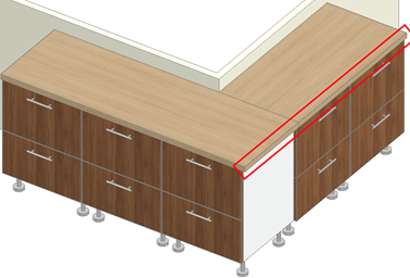
The inserted value creates an offset of the contiguous part to the front. A negative value results an inset of the contiguous parts. Use case: Oversize/ Projection at the work surface front The oversize/ projection of a work surface is applied when at least one of the contour segments is generated after an article front edge. Example:
|
| Oversize lateral for offset |
The entered value provides a lateral offset of the contiguous parts where there is an onset and inset. A negative value results an inset of the contiguous parts. |
| Vertical Offset | The contiguous parts will be shifted in vertical direction by the entered value. Positive values shift the contiguous part upwards. Negative values move the contiguous part vertically downwards. |
|
Snap to wall left/ Snap to wall right/ Snap to wall back |
Available for work surfaces only. With the options
in the Work Surface principle, you determine whether the work surface should be extended towards the left/ right/ back wall during creation, if the distance to the wall is less than 300mm. To change the Wall Snap mode of a work surface in an existing CAD order, select the work surface, switch to the iXplorer Parametrics Tab and change the settings in the iX Properties Palette. Note: When you update to version 15.0.01.112 or later, the prior functionality for automatically snapping to the wall in the back will be turned off. So mind that you will have to checkmark the box "Snap to wall back" in the Work Surface principle or in the iX Parametrics properties to keep the behavior from the earlier version. Availability in Configurator Controls for the snapping of worktop edges to walls can be defined in the Article XML using the following variables in the attribute @name.
Example: Checkbox <CHECKBOX name="___CP_WALL_SNAP_BACK" label="Snap to wall back" default="No" checked="Yes" unchecked="No" visible="TRUE"/> |
| Split between articles |
If this function is activated the split will be generated at a article gap.
Depending on the values set under Maximum length , a cut will automatically be made if necessary. |
| Contour continuation front/ back |
The function defines the way in which the contiguous part is orientated to the contour of the selected article. Follow back/ front The contiguous part is created parallel (with oversize as entered) to the article contour. Front/ Back straight The contiguous part is created parallel (with oversize as entered) to the article that is furthest forward. Front/ Back angled The contiguous parts are positioned diagonally to the outer corners on backsets or protrusions of articles. |
| Corner Joint front / back |
The corner joint sets the trims in corners (internal and external corner). symmetrical angle The distance from the corner to the left and to the right side is equal. The length of the chamfer can be defined via the function Chamfer/ Radius. asymmetrical angle The start and end angles may be entered separately. The length of both distances can be defined via the function Chamfer/ Radius and Chamfer 2. Arc If the button is active, the corner will be chamfered with an arc. The radius of the arc can be defined via the function Chamfer/ Radius. |
| Chamfer/ Radius front / back |
Chamfer The entered value defines the distance from the corner to the start- /endpoint of the chamfer. Radius The value defines the radius of the arc. Therefore the corner joint has to be set to arc . |
| Strip front / back / left / right |
If you apply a part definition to one of the entries (front, back, left, right) a part will be generated at this position. You can set the trims by clicking the diagram on the upper right. Via a click on the button behind the entry you will switch to the level of Part Definitions . |
| Height of the Strip |
The entered value defines the height of the base, the light valance and the crown molding. The height of the work surface is taken from the used part definition. |
|
Hor. reveal of the strip |
Only available for work surfaces! The generated strip will be moved by the inserted value related to the work surface |
| Tip valance | If this function is activated the contiguous part will be tipped to the side. It will be constructed horizontal. |
| String profile |
Via this function you can apply a SPP to the contiguous part. The SPP will be extruded along the edges of the contiguous part. Via a click on the button behind the entry you will switch to the level of the Stretchable Purchased Parts. The dropdown box contains the last used principles. |
| Run of the profile |
Using the pull-down list, determine along which edges of the contiguous part the moulding should be extruded. There are different possibilities: None, Front, Right, Back, Left, Front & Left, Front & Right, Back & Left, Back & Right, Without Back, Without Front, Without Left, Without Right and All Sides. |
Joint Parameters

Available for Work Surfaces only!
See Enhanced Joint Cuts for Worksurfaces for a detailed description.
| Parameter | Description |
| Active |
Activate or deactivate the joint parameters for the respective corner situation of the worksurface. If you check this box, the joint parameters become active. This means that when the Worksurface principle is assigned, the joint cut is automatically calculated based on the parameters if the respective angle is present at the worksurface corner. Users do not need to manually select a Splitting principle. If NOT checked, users will be prompted to select an appropriate Splitting principle after choosing a cut suggestion. Note: The joint parameters are included in the program since version iX 2023 SR2. When you update to iX 2023 SR2 and newer, the joint parameters of existing Worksurface principles will be filled with default values. The "Active" checkboxes will NOT be checked, so data administrators can decide for themselves whether to use the new function. |
| Radius | The radius defines the arc contour that forms the transition between the depth cut and the angle bisector. A value >= 0 must be entered. |
| Offset Measure |
Decide which parameter should be used for the path calculation: - Angle bisector offset - Joint offset Depending on your selection, the field for entering the desired value will be displayed. |
| Joint Offset | The joint offset is the perpendicular allowance measured for the joint cut. The joint offset is usually used as a parameter for calculation in corners =90° or =135°. |
| Angle Bisector |
The offset of the angle bisector is the perpendicular distance measured from the front edge of the panel to the start of the radius/ to the end of the diagonal cut. The angle bisector is usually used as a parameter for calculation in corners other than 90° or 135°. Even for angles other than 90° or 135°, the bisecting cut must be sufficiently deep to completely cut through the front edge profile of the panel. This cannot be adequately ensured by defining the joint offset alone. Specifying the offset of the angle bisector and the radius ensures that the bisecting cut is sufficiently deep. The value for the offset of the bisector can also be modified by the designer or the salesperson during planning. As a convention, the offset of the bisector should be slightly greater than the thickness of the worktop front edge profile. |
Stretchers
Not available for worksurface!
| Part Definition |
Defines the Part Definition for Stretchers If a principle is selected here, the stretchers will be inserted in the construction. |
| Stretchers between articles | If the function is enabled, an additional stretcher will be inserted in the gap between the articles. |
| Type |
Is only enabled if "Stretchers between articles" has been enabled. For the stretcher in the gap between the articles can be defined if whether a simple or a double strip is inserted for the stretcher. |
| Independent Stretchers |
Defines the reference for the linear division. The linear division refers to the width of a single article for "Per Article". The linear division refers to the complete width of all articles for "Across all Articles". |
| Linear Division | Refers to the positioning of the Independent Stretchers. |
| Bottom Reveal | Distance of the stretchers to the bottom edge of the base. |