
Group 2D Drawing Views
Access
Ribbon : Drawing Views > 2D Drawing Views
General Information
The group 2D Drawing Views offers tools for creating, dimensioning and annotating 2D views. Special cases are
You can configure the section labels and symbols individually. See Configuration of section labels and symbols .
View/ hide iX sections in the drawing area
Using context menu options in the drawing area, you can quickly show and hide the sections created by iX , including annotations and dimensions.
Hiding sections improves the graphics performance, tidies up the drawing area and makes designing in CAD easier.
Methods for the standard creation of views
| Refresh View |
Calls the dialog Section options . After selecting the section that needs to be change, the current settings are shown and can be modified. |
| 2D plan view |
Creates a plan view whereby a section is placed slightly above the highest selected element. After the function is called, all elements must be picked that are to be included in the section.
Please, note that walls must be completely selected to include them in the section. Besides, mind that only 3D solids can be displayed in the section. For example, purchased parts consisting of 3D surfaces are not displayed in the section. The function opens the imos Section options dialog. |
| Create 2D Elevation View |
Generates a section derived from a 2D plan view. The section plane is defined by means of a reference flag/ arrow, for which you can define an insertion point and a rotation angle. The area that a view should display can be limited to the left, to the right and to the back. See View boundaries. When the function is called, the imos Section Options dialog opens. |
| New section |
The function determines the section level of a part or an article. Sections can be made for any type of view and shows the section's surface and all the parts that are behind the section level. Refer also New section |
| Clip section | You can interrupt a section to delete irrelevant information and simplify the drawing. After starting the function, a rectangle must be created. The rectangle defines the area that will be deleted. The section drawing is now cropped. The remaining distance can be defined. |
| Part views |
Cause labeling and indexing for machinings and edges. If you select a part after calling the function, the dialog Section Options opens. In this case, imos uses the last used dimensioning principle. If the function is started for the first time you must first press ENTER before you pick a part. The Element Manager then displays the Dimensioning principles and it is possible to select a principle. After you click Apply, select the corresponding part in the drawing. Dimensioned part views are created, which can then be dropped into the model space. |
| Delete View | Deletes the view and the description texts. After calling the function the elements that should be deleted can be selected with the mouse. |
| View Dimensioning |
Creates the outside article dimensions of a section. It is an associative dimensioning. Choose one of the following options in the command line:
When the function is called you will be requested to select a block reference. Pick the section to be dimensioned using the mouse pointer.
The settings of the dimensions depend on the settings in the STANDARD dimension principle and thereby on the dimension style IMOS_DIM.
Unlike the 2D plan and elevation views you can dimension a section even when you have not inserted a room. You may, e.g., make a section from a side view to create a plan view. |
| Section Dimensioning |
Dimensions the constructive details of a section. When the function is called you will be requested to select a block reference. Pick the section to be dimensioned using the mouse pointer.
The settings of the dimensions depend on the settings in the STANDARD dimension principle and thereby on the dimension style IMOS_DIM. |
| Associative section dimensioning |
Insert associative dimensions manually. Here you assign each dimension point clearly to one object. As a result, the dimension points also move when the object's dimensions change. This feature supports linear dimensioning only. Objects where you can select points as dimension points:
Objects where you cannot select points as dimension points:
Prerequisite: In AutoCAD Options> User Preferences Tab> Associative Dimensioning, the check-box “Make new dimensions associative” is enabled. Procedure:
|
| Annotate view |
After calling the function in the Element Manager an Annotation Principle can be selected. Corresponding to the settings of the Annotation Principle, the selected view will be annotated. In this case DWG blocks serve as annotation, which can be created or adapted to suit user-specific requirements. It is possible to use pure texts, imos attributes, symbols through to dynamic blocks. |
| Annotate manually |
Add a single individual annotation. From your collection, choose a data block and select section (view) elements that you want to apply the annotation on. By default, the application loads the block you selected the last time. Click [Select data block] in the command to choose a different block in the "Load block" dialog. In the drawing area, click on the object you want annotate and left-click where you want place the annotation. If the block is not-annotative, you can scale the block by moving the cursor or by typing in a specific scale factor; Left-click to apply the scaling. Optionally, you can place a leader arrow with another left-click. Otherwise, press ENTER to finish the process and to insert another block - the same scale factor and default settings are kept. To exit the tool completely, press ESC. The single annotations are assigned to their own layer. The layer label is composed of: <Layer name of the affected section> + .ManualAnno . Example: "imosSectView.2.ManualAnno". |
| Index part |
Additional information can also be output for the parts of a section. Read the chapter Index/ annotate part . |
| Delete Annotation | Deletes the article or part annotation of the selected section. |

Views optimized for work surfaces and house installations
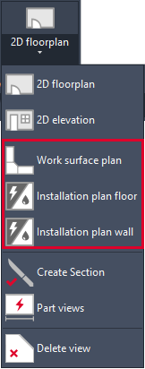
Next to the standard floor plans and elevation views, you can use the following methods to specifically generate views for work surfaces and house installations in a quick manner.
| Method |
Description |
| Work surface plan | When you launch the method, all work surfaces in the drawing will be isolated so that you can easily create a floor plan that contains the work surfaces only. You can make adjustments in the "Section options" dialog before you apply with a right-click. The article isolation will be lifted in the end. |
| Installation plan floor | When you launch the method, house installations in the drawing will be isolated so that you can easily create a floor plan that contains the house installations only. You can make adjustments in the "Section options" dialog before you apply with a right-click. The article isolation will be lifted in the end. |
| Installation plan wall/ view |
Analogous to a standard 2D view, place an elevation indicator in the floor plan for installations and adjust the section options if required before you with a right-click. Note: When you place the elevation indicator in a standard floor plan, the installations will not be specifically isolated. |
Assistants for creating 2D views
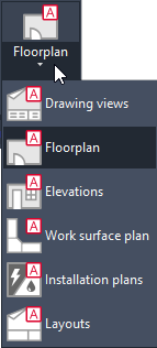
New assistants take over some of the work steps when creating 2D views; At the same time, the section options in iXplorer allow views, annotations, dimensionings, and layouts to be configured as individually as possible.
| Function |
Description |
| 2D Drawing Views |
A floor plan, elevation indicator, and associated views are generated. The drawing views are placed at a distance of 4000mm south of the 3D objects and existing drawings. The creation of elevation indicators is article-related. Fixed sets of rules apply. See Create a floor plan without walls with wizards . |
| Assistant Floorplan |
Select objects in the drawing area and adjust the section options in the iXplorer properties palette if required. Right-click to apply the selection. The application creates the floor plan and automatically places it south of existing objects in the drawing, with a distance of 4000mm. Additionally, the section label will be inserted at the bottom-left of the floor plan. The creation of elevation indicators is article-related. Fixed sets of rules apply. See Create a floor plan without walls with wizards . Using the assistant for elevations, you create the elevation views for the elevation indicators. |
| Assistant Elevations |
To create the elevation the elevations, select one or more elevation indicators and apply the selection with a right-click or with ENTER. Like the floor plan of the Assistant, the elevations will be placed south of existing objects in the drawing, with a distance of 4000mm. Optional: Before or after using the assistant, you can change the boundaries of the view. See View boundaries. Tip: Use the rectangular selection to speed up the process - the program automatically filters the selection by elevation views. |
| Assistant Work surface plan | All work surfaces in the drawing will be isolated so that you can easily create a floor plan that contains the work surfaces only. You can adjust the sections options in the "Section options" dialog and select relevant objects in the drawing area. Subsequently, the work surfaces will be generated. Place it in the drawing area - the section label will be inserted at the bottom-left of the floor plan. |
| Assistant Installation plan |
All house installations in the drawing will be isolated so that you can easily create installation plans. You can adjust the sections options in the "Section options" dialog and select relevant objects in the drawing area. Subsequently, the floor plan will be generated. Place it in the drawing area - the section label will be inserted at the bottom-left of the floor plan. The application creates the elevation views and places them south of existing objects in the drawing, with a distance of 4000mm. Note: The application will create a floor plan even when there are house installations in the walls only, because an elevation view is always derived from a floor plan. |
| Assistant Layout |
In the iX properties palette, select one of the options:
Note: The dialog does not close by itself. Click "X" to close it. |