Drawing views with enhanced features
View boundaries
By default, everything that is in the line of sight of the elevation indicator is displayed in a view.Limit views to the left and right sides, as well as to the back, to focus on articles of your choice and hide the rest.The elevation indicator only references articles within the boundaries that you specify.
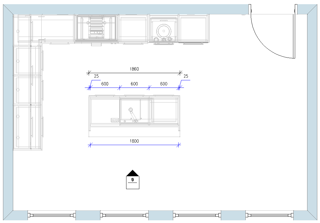
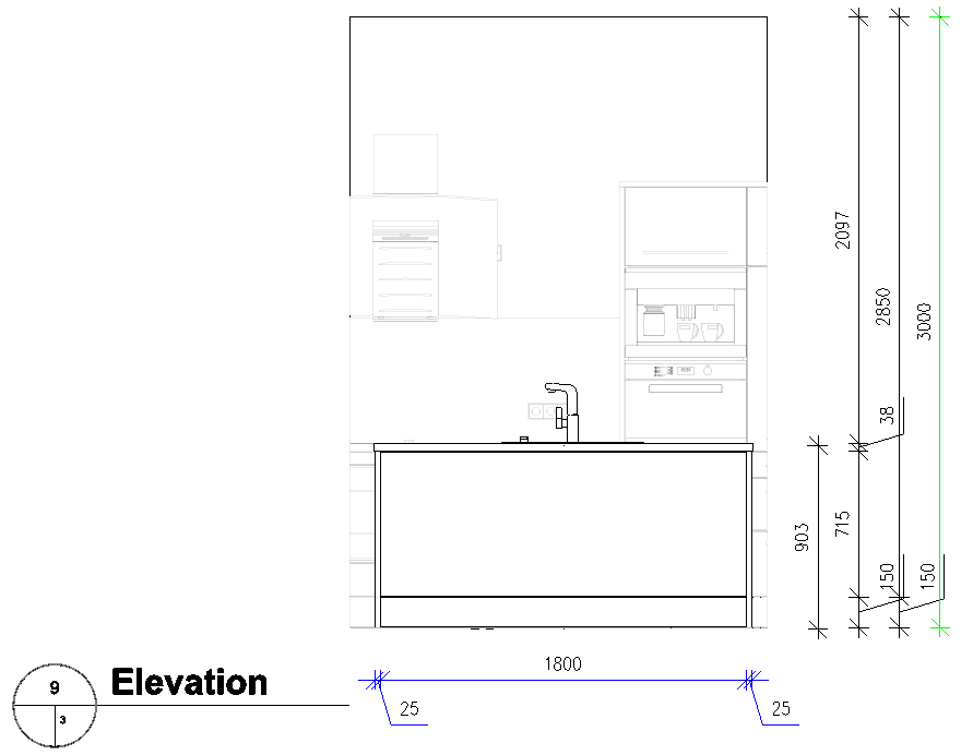
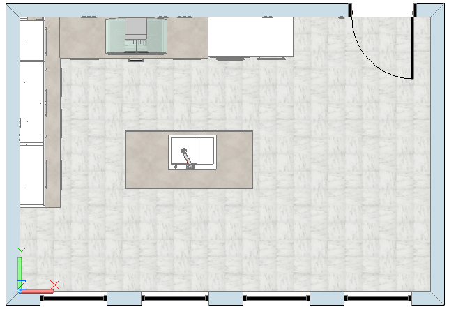
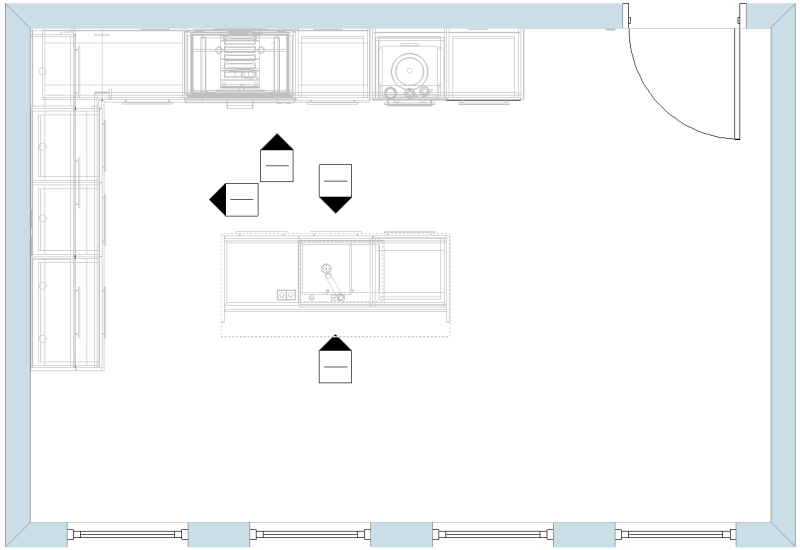
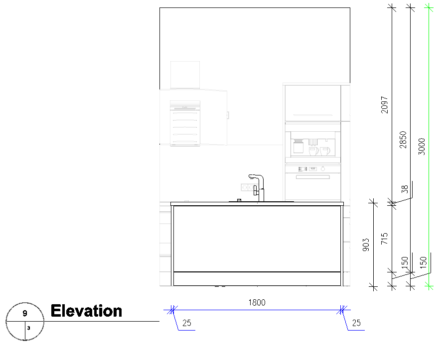
By default, the depth of view (limit at the back) is infinite.In the example shown, the elevation indicator "sees" not only the kitchen island in the foreground, but also the kitchen unit in the background.However, you can change the depth of view as you prefer.
The procedures are described below.
Create a view with or without a boundary
Prerequisite: A floor plan that was created with iX methods.
-
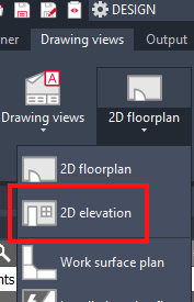
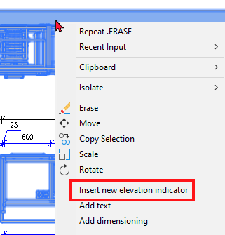
Go to Drawing Views menu > 2D Drawing Views group and click 2D View. Or use the Insert New Elevation Indicator function in the context menu of the floor plan.
-
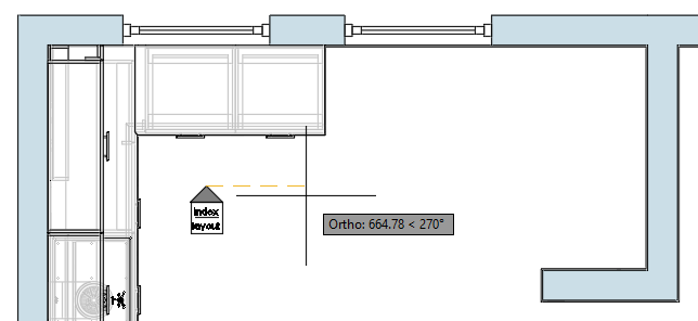
Place the elevation indicator and align it.
A guide line appears on the mouse pointer. It indicates the left boundary.
-
If you don't want to set any boundary, press ESC.
If you want to set boundaries, proceed to the next step.
-
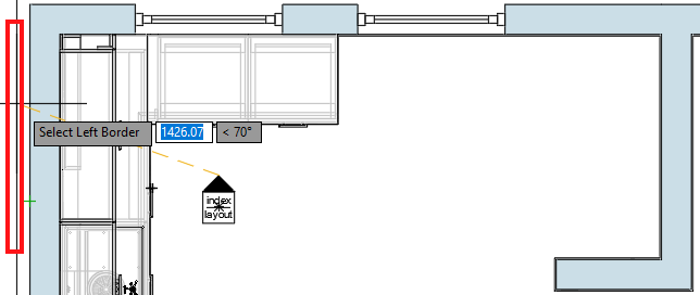
Move the mouse pointer to where you want to set the left boundary, then left-click. A new guide line will appear on the mouse pointer. It indicates the left boundary.
-
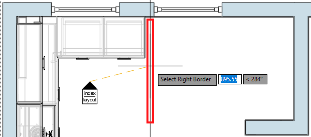
Move the mouse pointer to where you want to set the right boundary, then left-click.Subsequently, the 2D view with the defined boundaries is generated.
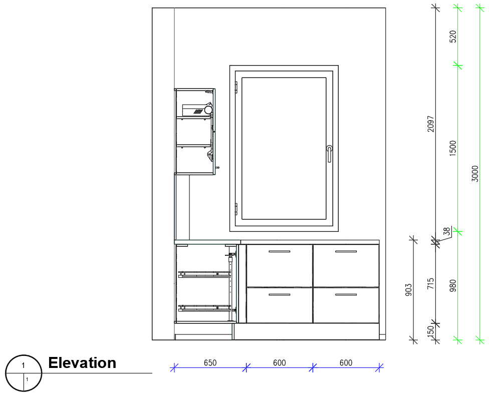
Change the boundary of the view
-
Click on the elevation indicator in the floor plan.A line is displayed that lays on the elevation indicator and is perpendicular to it.This line marks the view depth.
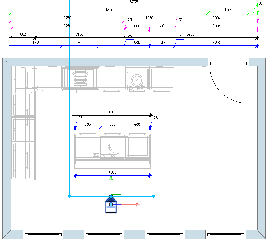
-
Select one of the round grips, move the line as you wish and apply by right-clicking.
The left grip shifts the left boundary.
The right grip shifts the right boundary.
The grip in the middle shifts the rear limit/ depth of the view.
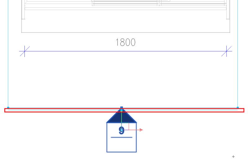
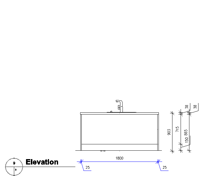
Example: Move the view depth "behind" the kitchen island to hide the kitchen unit in the background.
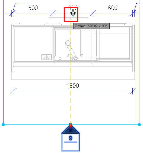
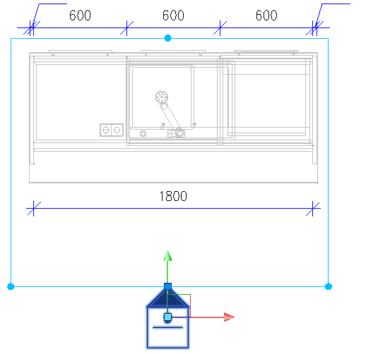
The illustration on the right shows the rectangular section, which is formed by the boundaries left/ right and the view depth.
-
Click Refresh View in the menu.

- Select the views you want to update.
Result: In the example, the objects that lie behind the set view depth are no longer displayed in the 2D view.
Create a floor plan without walls with wizards
From iX 2023 the automatic creation of elevation indicators is article-related.Accordingly, the wizards Drawing Views (A) and Floor Plan (A) no longer require walls to generate the elevation indicator.
As a reminder: In iX 2021, elevation indicators could only be set automatically if articles were placed in front of a wall with a minimum distance of 1000mm. The alignment of the elevation indicator was perpendicular to the respective wall.
Note: The default value of the view depth in room divider situations changes from 2000mm to 1800mm. This setting has nothing to do with the new article view, only with the room divider view.
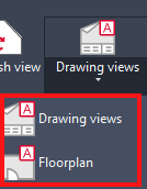
By clicking on one of the wizards Floor Plan (A) and Drawing Views (A), you can create floor plans with elevation indicators that the program sets itself.
A fixed set of rules applies:
- to determine the boundaries left/ right
- to select the articles for which a view will be created.
Rules
-
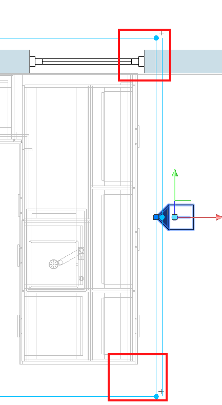
Limitation left/ right: When limiting a view, imos automatically adds 300mm to the left and right of the depicted articles.
-
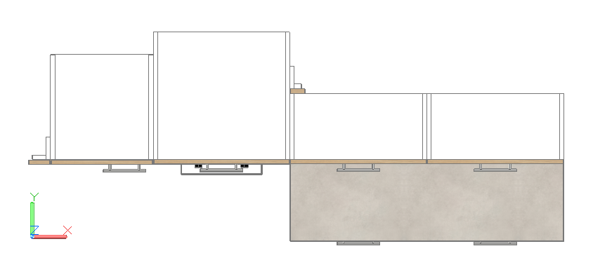
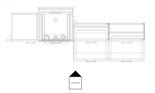
Articles for which a view is generated: All identically aligned articles are displayed in one view.
-
In exceptional cases, multiple views are generated: Articles are identically aligned, but have a distance >1400mm
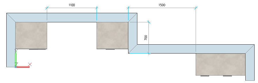
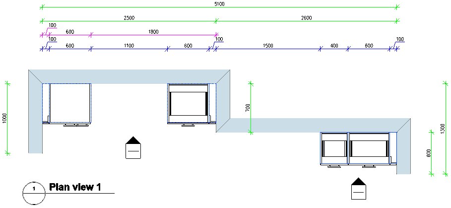
Articles are aligned identically, but the back edges of the articles have a distance of > 800mm
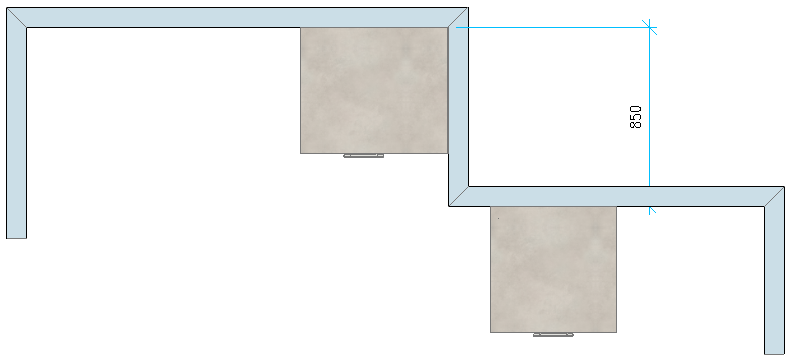
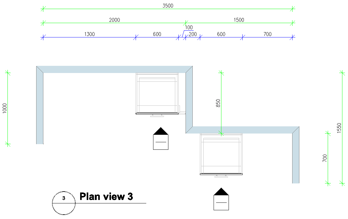
There are corner articles in the floor plan.For each corner article, a view is created from the front and from the side.
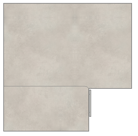
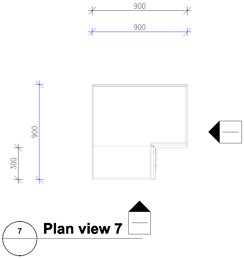
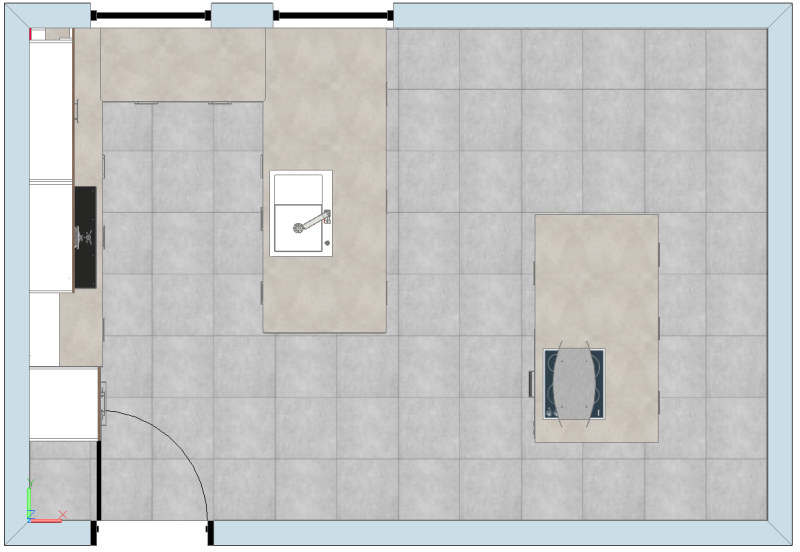
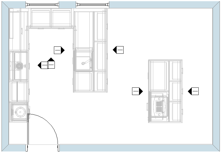
Example:
Floorplan (A) creates a floor plan with the following automatically set elevation indicators.