Drawing output
Configuration of section labels and symbols
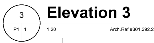
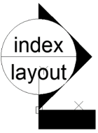
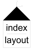
The drawing output in iX 2023 relies on configurable section labels and reference symbols that you can adjust to your individual company specifications.
Your options include:
- Configure section labels or reference symbols in their size either fixed or annotative.(annotative = object adapts to the set scale)
- Configure texts in the reference symbols so that they are always "correctly" aligned and thus remain readable.
- Customize the color and style of article section lines.
- Use newly built-in imos attributes or user-specific attributes to depict labels and references.
The configuration is done via corresponding DWG files, which are located in the imos configuration directory.(%APPDATA%\imos AG\<program version>\config\ DrawingFlags\)
Example views:
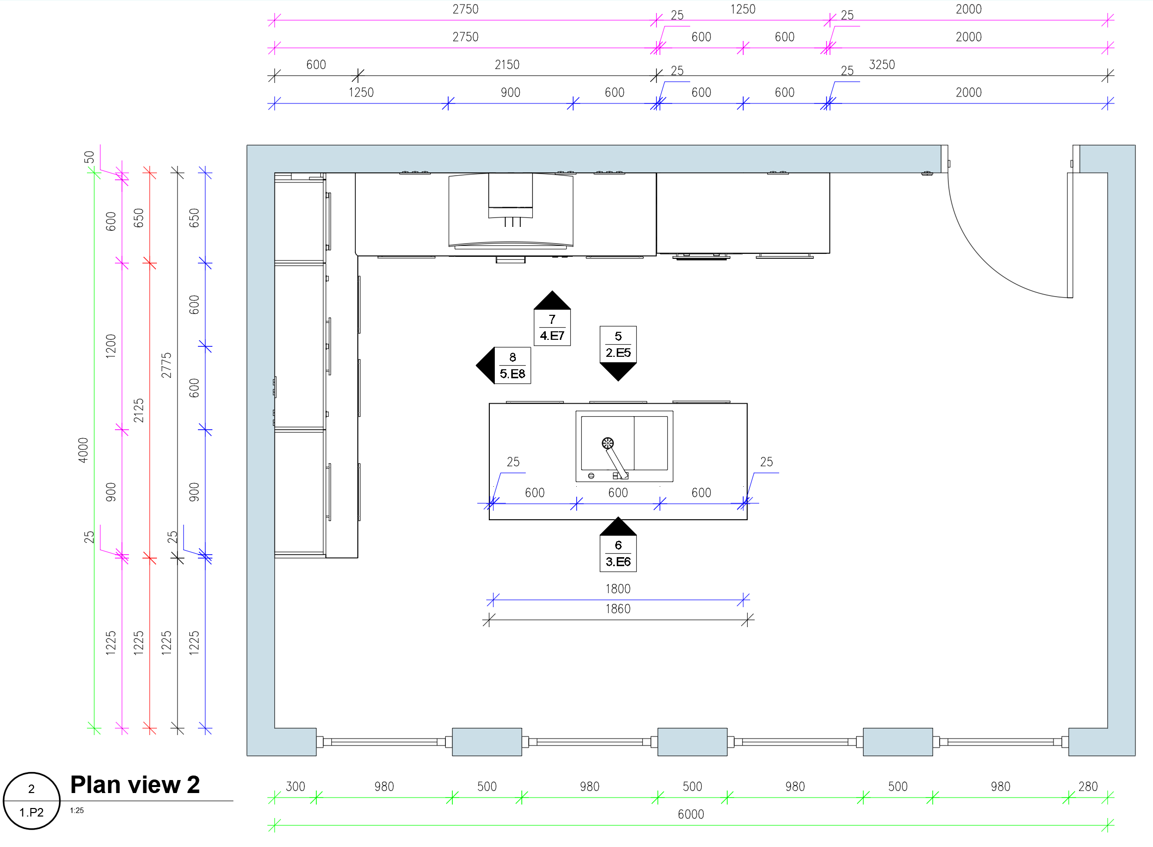
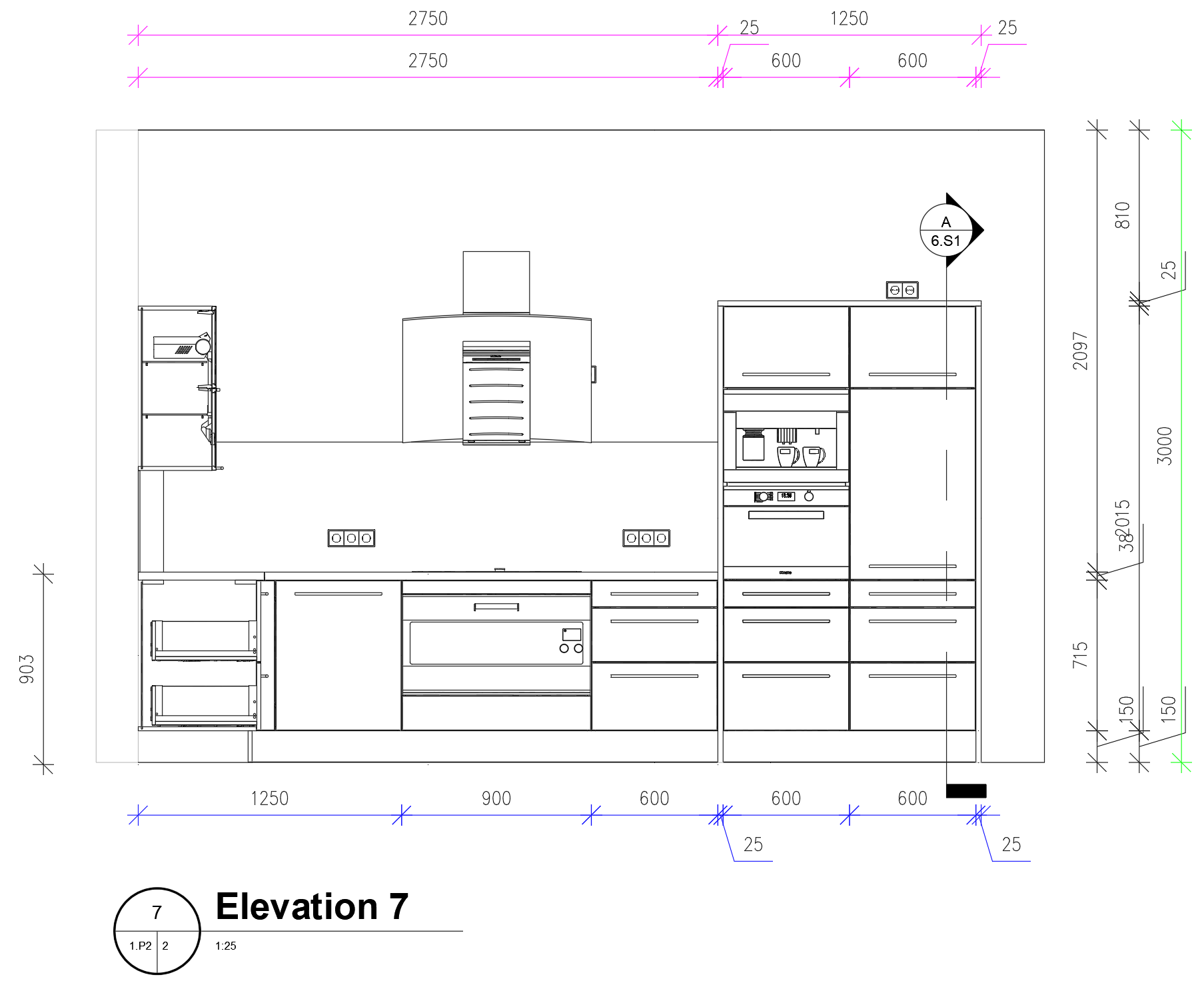
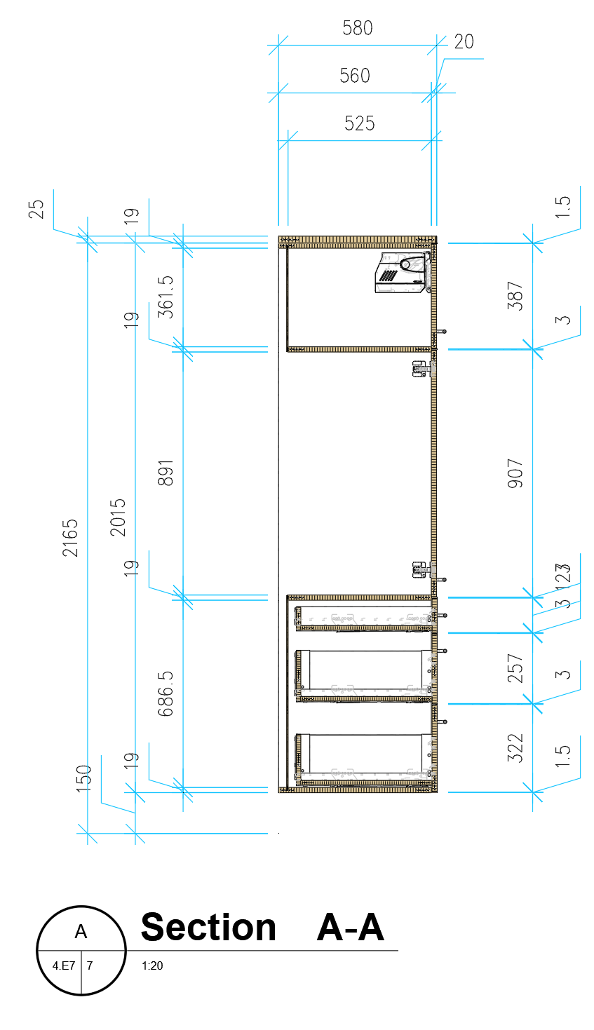
The following chapters describe in detail the configuration of section labels and reference symbols.
Application
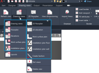
The new section labels and symbols are used when one of the following iX drawing output functions or assistants is applied:
- Drawing Views
- Floor plan
- Elevation
- Section
- Worktop plan
- Installation plans
- Installation plan floor
- Installation plan wall
Compatibility
If existing orders still contain drawing views with "old" section labels and symbols, the old functionality for refreshing drawings will still be executed for compatibility reasons.
If the new function is to be used for an existing order, you must first delete the drawing views for this order and then create them anew:
- Delete views
- Run the _PURGE (all) command
- Creating new drawing views
If the "old" function should also be used for new orders, please contact the imos service or an imos sales partner.
Info Partner: In the imos.INI, set LEGACY_SECTION_LABELLING=1.
Configuration
General
The section labels and symbols are configured via DWG files located in your CONFIG directory: %APPDATA%\imos AG\<Program version>\config\DrawingFlags\
| Configuration DWG | Description |
| imosLabelPlanview.dwg | Labeling of floor plans |
| imosLabelElevation.dwg | Labeling of views |
| imosLabelSection.dwg | Labeling of sections |
| imosFlagsElevation.dwg | Symbol/ flag for views |
| imosFlagsSection.dwg | Symbol/ flag for sections |
Annotativity
In general, the delivered DWGs are annotative.This means that the size of texts and symbols always remains the same in the paper space – regardless of the set scale.
Note: AutoCAD saves the position of annotative elements depending on the scale.For example, if you move the label of a view, that move applies only to the scale that is set at the time.
When you create new configuration files, note the following points:
If you want the labels and symbols to be annotative, the entire DWG file must be set as annotative.The individual elements (lines, texts, attributes) within the DWG must not be annotative.
To make the DWG file annotative, use the _ANNOTATIVEDWG command and set the value to 1.

Also, make sure that the scale is set to 1:1 in the model space and that there are no other scales within the file.Otherwise, scaling problems at certain scales may occur later.
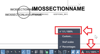
Therefore, delete all scales except the "1:1" scale:
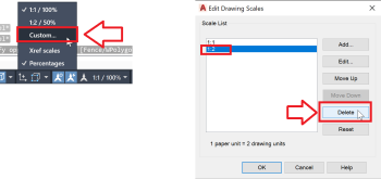
- Go to Status Bar > Scale > Custom... The "Edit Drawing Scales" dialog opens.
- Select all scales other than "1:1" and click Delete.
Dynamic elements
Info: How to use the block editor and dynamic elements is described in the AutoCAD help.
Some configuration DWGs contain dynamic elements, for example, to be able to extend or shorten lines for the section labels.
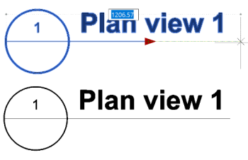
When opening such files, a message from AutoCAD appears:
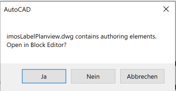
By clicking Yes, you can edit these elements via the block editor or create them yourself.
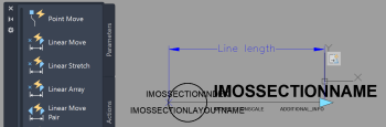
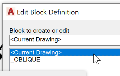
If a configuration file does not yet contain any dynamic elements and you want to create them, proceed as follows:
- Open the configuration DWG with AutoCAD
- Enter the command _BEDIT
- In the Edit Block Definition dialog, select <Current Drawing>
- Create and edit dynamic elements in the block editor
Available attributes
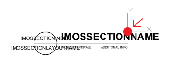
Suitable IMOS attributes have been built in for the section labels and symbols.You can use them as needed.
Example:
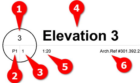
- Index number of the section
- Layout name of the parent section
- Index number of the parent section
- Name of the section
- Scale
- Custom field
Also, the tag ADDITIONAL_INFO allows you to add custom attributes in the configuration DWGs (No. 6 in the screenshot above).In generated drawings, double-click on the attribute to fill or edit it (e.g. with architect reference numbers).
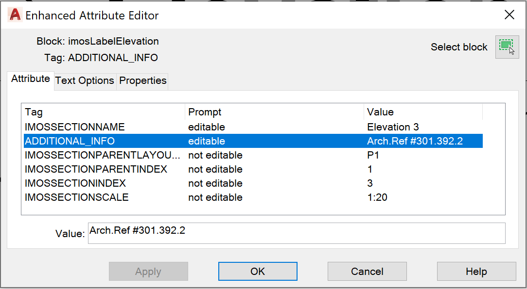
The following IMOSATTRIBUTEs can be used in the configuration DWGs:
| [IMOSSECTIONINDEX] | Specifies the section number or index number. |
| [IMOSSECTIONNAME] |
Section name. The default for creating a new section is as before: "Grundriss" [GER] | "Plan View" [ENG] "Ansicht" [GER] | "Elevation" [ENG] "Schnitt" [GER] | "Section" [ENG] The section name is editable and can be adjusted by the user later. |
| [IMOSSECTIONSCALE] | Scale from the viewport of the layout to which the section is linked (see function "Link view"). |
| [IMOSSECTIONPARENTINDEX] | Section number or index number of the parent section. |
| [IMOSSECTIONPARENTNAME] | Section name of the parent section. |
| [IMOSSECTIONLAYOUTNAME] | Name of the layout to which the section was linked (see function "Link view"). |
Note: Only the IMOSSECTIONNAME attribute is editable and updates its references.You should not make manual changes to other imos attributes to avoid inconsistencies.
Section labels
For each section type (floor plan, view, article section), the section names are configured via their own DWG – so they are independent of each other.
The insertion point of the section labels is always the zero point of the configuration DWG and can therefore be manipulated accordingly.
Symbols (flags)
The configuration of the symbols (also called "flags") is slightly different from that of the section labels.What you need to pay attention to, you will learn in the following chapters.
Symbol for views
The symbols for views are configured via the "imosFlagsElevation.dwg".
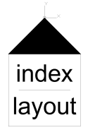
It is crucial that the text always remains legible, no matter in which direction the view is generated.
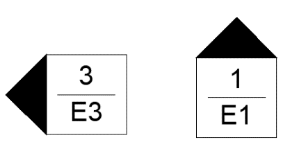
Therefore, the DWG imosFlagsElevation contains two blocks:
| Block | Description |
|
imosFlagElevation |
Represents the symbol.This block always rotates with the section line. |
| imosFlagElevation_Text | Contains the text.Depending on the angle at which the view is generated, imos iX rotates this text block so that it always remains legible and does not "stand upside down". |
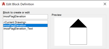
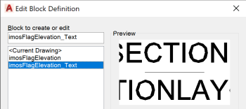
Mind the interaction of both blocks when making changes to this symbol.
Symbol for sections
The symbols for article sections are configured via the "imosFlagsSection.dwg".
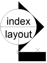
As with the "Symbol for views" (Symbol for views), the DWG consists of several blocks, so that the individual elements can be configured differently:
Again, a distinction can be made between symbol and text so that the text always remains legible.
In addition, the symbols at the ends of the line can be adjusted differently.
The DWG imosFlagsSection contains the following blocks:
| Block | Description |
| imosFlagSectionStart | Represents the start symbol of the section line.This block always rotates with the section line. |
| imosFlagSectionStart_Text | Contains the text for the start symbol.Depending on the angle at which the section is created, imos iX rotates this text block so that it always remains legible. |
| imosFlagSectionEnd | Represents the end symbol of the section line.This block always rotates with the section line. |
| imosFlagSectionEnd_Text | Contains the text for the end symbol.Depending on the angle at which the section is created, imos iX rotates this text block so that it always remains legible. |
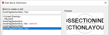
Info: In the delivery data, no text is used for the end symbol, only a symbol.Therefore, the block "imosFlagSectionEnd_Text" is missing here.If you also want to configure a text for the end symbol, then create and fill the mentioned block.
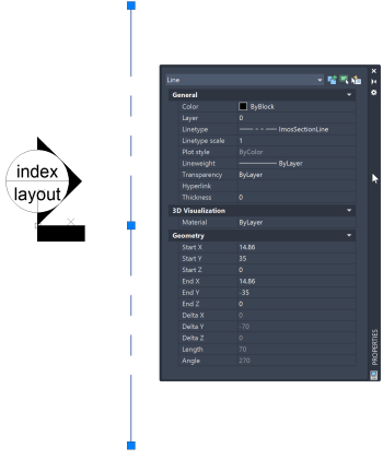
In addition to the symbols, you can also configure the section line itself.This is also located in the configuration DWG.
imos iX takes over the settings you make.For example, you can change the line type or color.
Document Manager – Dynamic blocks for articles
In the Document Manager, you can use dynamic or parameterized blocks at article level that depict additional article information.These range from individual attributes or variables to complex dynamic blocks with individual graphics.
Use dynamic blocks to depict information and details when a generated view from the order drawing can't depict them.
To create dynamic blocks, you use standard AutoCAD functions and the AutoCAD block editor.With it you can use imos attributes and variables to control the block.
During the Document Manager output, the attribute block or the dynamic block is assigned the used order and article-related variables, imos CAD attributes (e.g. IMOSARTICLEHEIGHT) and PXM attributes (e.g. COND. GROUP_CPINFO1).
Note: The "$" character in front of the imos variables cannot be evaluated in AutoCAD functions.Therefore, omit the character.
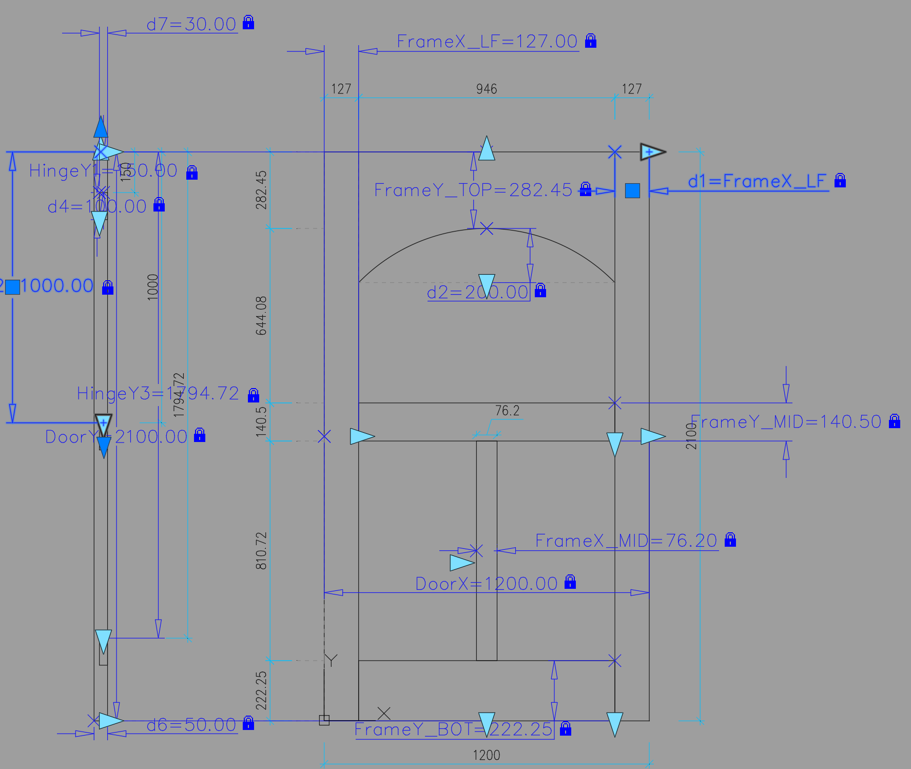
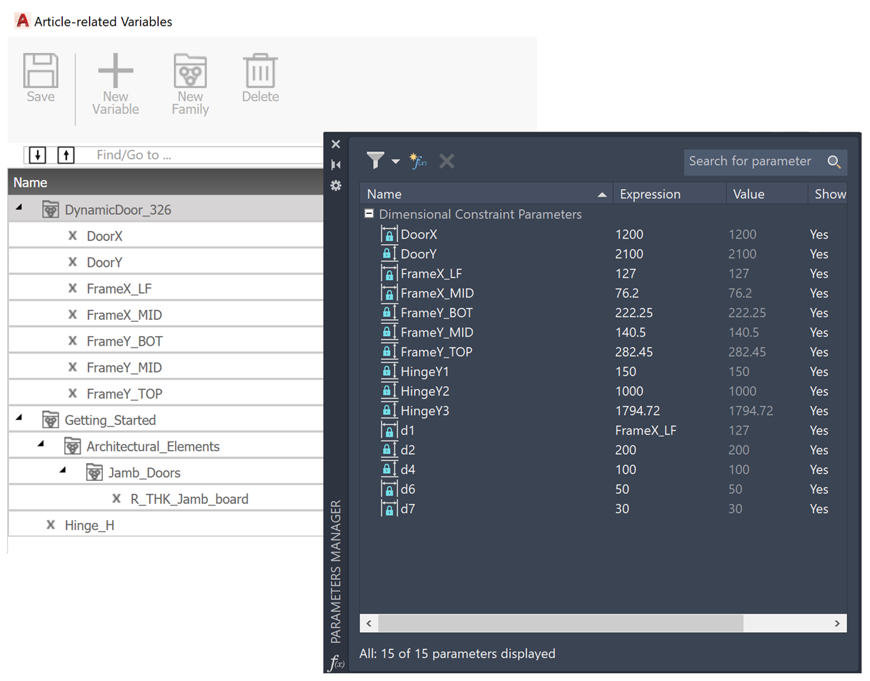
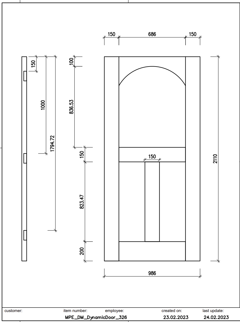
Example: DWG with door as a 2D drawing that is parametrically dimensioned.The dimensions are referenced here from imos variables.
Procedure
Prerequisites: The desired attribute block is located in <Library>\AttDWG – either as a separate DWG or in imosBlocks.dwg
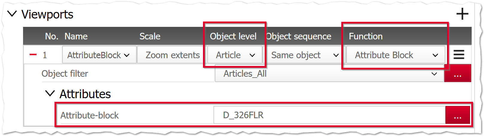
- Go to Document Manager principle > Viewport. Expand the desired viewport.
- Make the following settings:
- Scale factor = Best scale or = Zoom
- Object level = Article
-
Function = Attribute block
The Attribute block field becomes visible in the Attributes area.
-
Attribut block = <Block name or DWG>
Select the block DWG using the 3-dots button or enter the block name directly.The program then searches for a DWG with the same name.If it doesn't find the file, it looks for a block with the same name in the imosBlocks.dwg.
Variables: It is possible to enter imos variables in the Attribute Block field. The program then searches for a DWG file with the variable name in the <library>\AttDWG directory. You can use the variable to control which DWGs are to be referenced for the respective article.
-
Save the principle.
The function (or attribute block) is applied during the Document Manager run to each article that meets the condition defined in the Object Filter field of the viewport.
"Quick" part dimensioning
As of iX 2023, the "Quick" part dimensioning now uses the Dimensioning principles introduced in iX 2021.This changes the workflow as follows.
The function call is still made via the corresponding button in the ribbon menu.
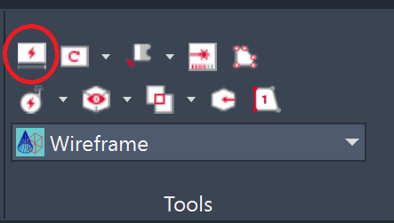
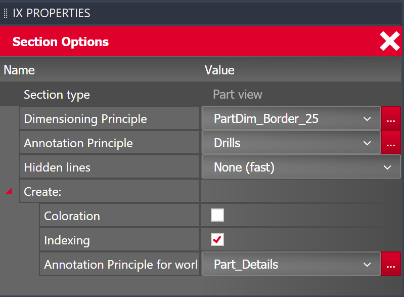
After clicking on the button, the options for the Quick part dimensioning appear in the iX Properties palette. Here you can select the desired settings for the dimensioning or leave the settings unchanged. imos always loads the settings most recently used at this point.
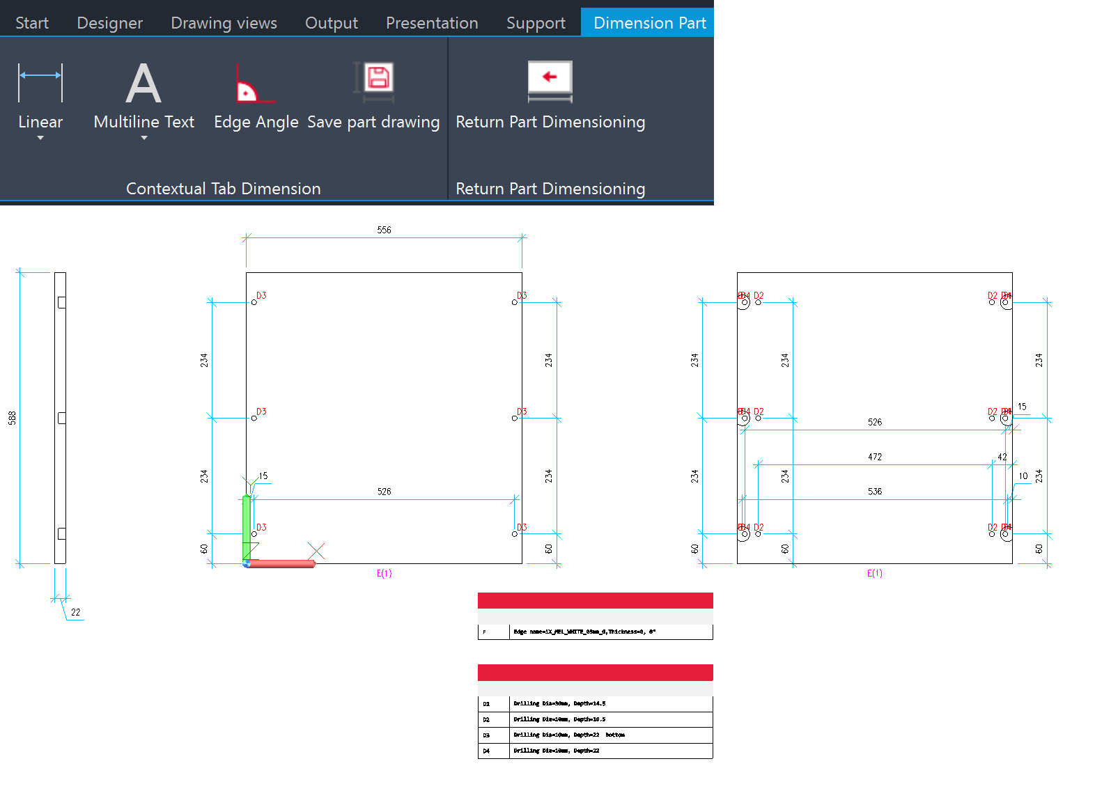
While the iX Properties palette is displayed with the dimension settings, the Pick mode is active.As soon as you have picked a part, it is dimensioned with the set preferences.The view and the ribbon menu then switch to Quick part dimensioning mode.In this mode, the ribbon offers functions for manual dimensioning, manual labeling or for saving the drawing in a DWG.The Go back button takes you back to the previous view and you can continue working.
The Quick part dimensioning supports both single parts and multi-parts.In the case of a multi-part, you are asked in a dialog whether the multi-part should be dimensioned as a whole or whether the picked child part should be dimensioned.