
Solid wood joints
iX 2023 SR1 allows you to create data for simple solid wood joints such as mortise and tenon or box joint connections.
To do this, you primarily need the following properties in the connections of a connection situation.
- Definition via = Groove construction, division along part edge
- Groove construction
- Linear Division X
The combination of these properties defines the division of a groove construction along a part edge.
For example, mortise-tenon connections can be created by defining multiple connections within a connection situation that create necessary cutouts in the parts. Or you can create a simple box joint connection by specifying a corresponding linear division in the connection at the respective edge.
Find out how to create solid wood joints in the examples.
Examples
Download sample data
Note: We recommend that you do not import sample data into a production database, but into a separate test database.
You can download sample data here: SolidWoodConnections.zip
Variables used
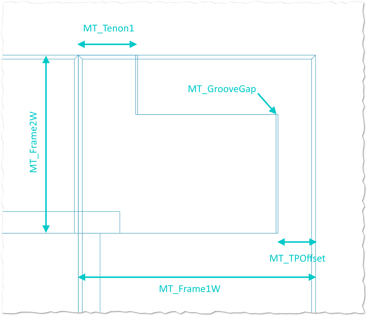
The following variables are used in the examples:
|
$MT_Frame1W („Mortise Tenon Frame 1 Width”) |
Width of a type 1 frame part Default: 120 |
|
$MT_Frame2W („Mortise Tenon Frame 2 Width”) |
Width of a type 2 frame part Default: 90 |
|
$MT_GrooveGap (“Mortise Tenon Groove Gap”) |
Tolerance gap Default: 1 |
|
$MT_Tenon1 (“Mortise Tenon Tenon 1”) |
Length of shorter tenon Default: 30 |
|
$MT_TPOffset (“Mortise Tenon Tenon Part Offset”) |
Value by which the tenon part should be shortened compared to the total frame width Default: 20 |
|
$MT_max_PrfThk (“Mortise Tenon Maximum Profile Thickness”) |
Profile width |
|
$MT_FrameWPrf (“Mortise Tenon Frame Width Profile”) |
$MT_Frame1W-$MT_max_PrfThk |
| $BoxJointDiv |
Linear division of box joint connection |
Example: mortise-tenon connection without profile
Overview
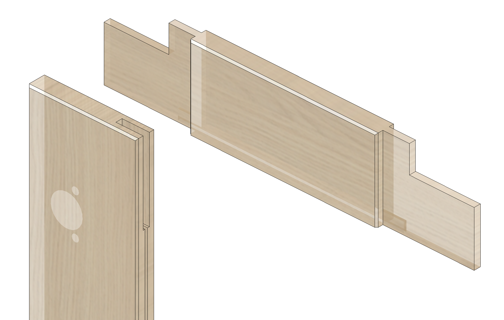
We want to create a frame door as a multi-part-element and connect the individual frame parts with mortise and tenon.We proceed as follows:
- Use the Part Editor to create a frame construction consisting of four parts.The parts must intersect so that the desired cutouts can be created by means of groove constructions.
- In each frame part definition, assign connection situations to the edges that are to create a mortise&tenon joint.
- The assigned connection situation has 3 connections of the type "Groove construction, division along part edge".This makes it possible...
- to divide the mortise&tenon connection into sections
- to assign a corresponding groove construction per section, each of which generates a portion of the mortise&tenon connection.
Info: The orientation of an edge connection (in the part definition) can be "reversed" if necessary to "mirror" the orientation of machinings on the left/right.This allows you to reuse the same connection.
Data set-up in detail
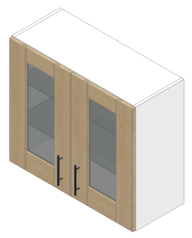
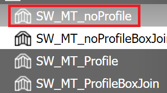
The article called "SW_MT_noProfile" is a kitchen cabinet with a double door. Both leaves of the double door have the same frame construction. The frame parts are connected with mortise&tenon.
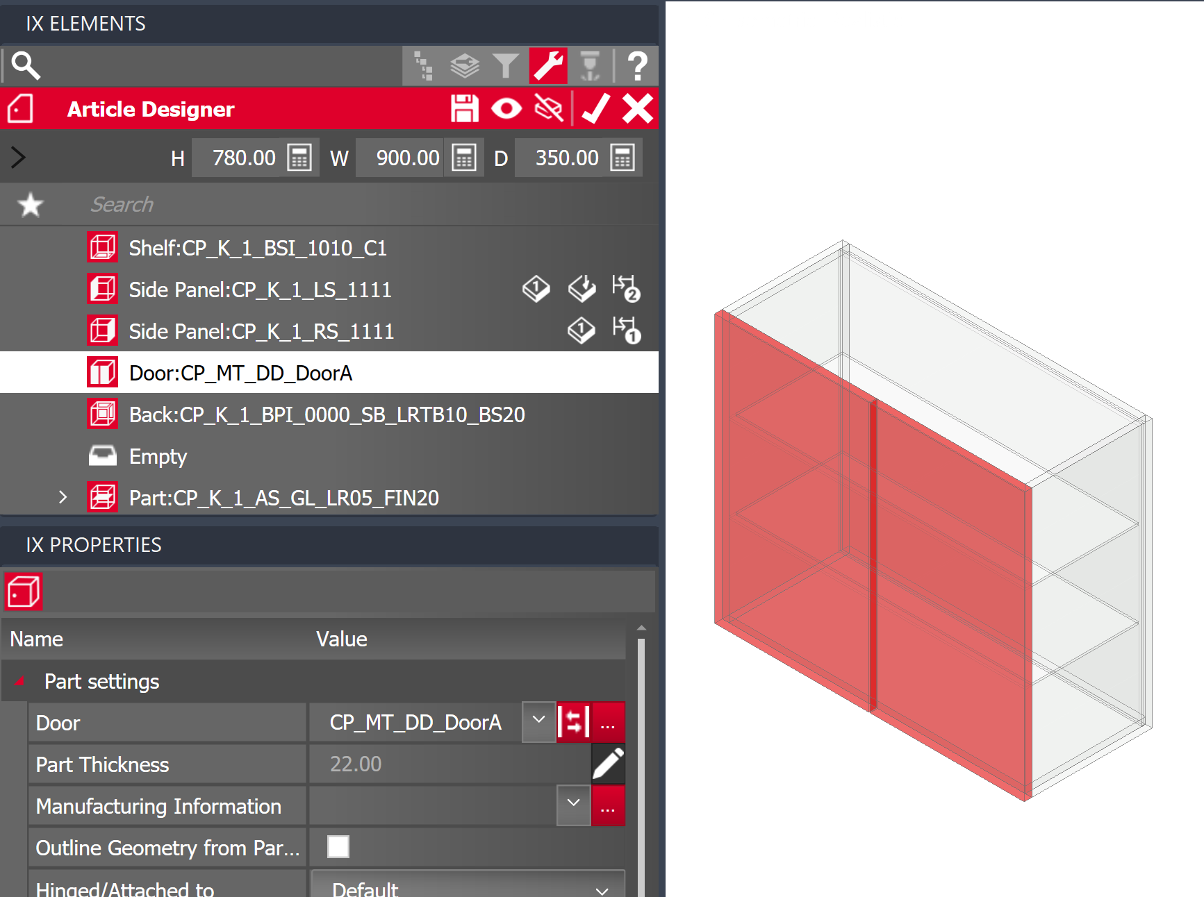
The cabinet door is assigned the Construction principle "CP_MT_DD_DoorA".
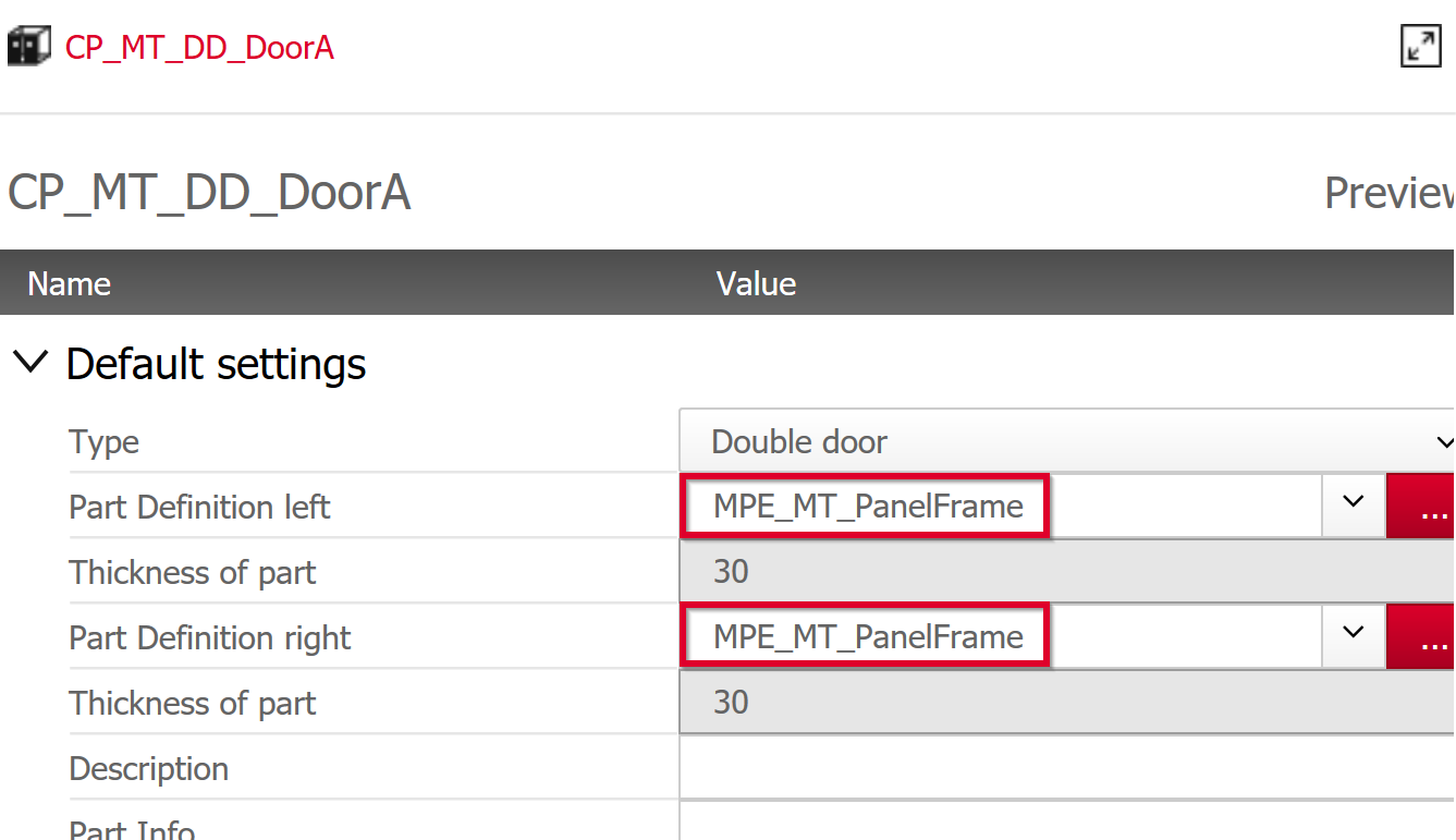
In the Construction principle, the part "MPE_MT_PanelFrame" is assigned to the left and right door leaf. Here we deal with a multi-part element.
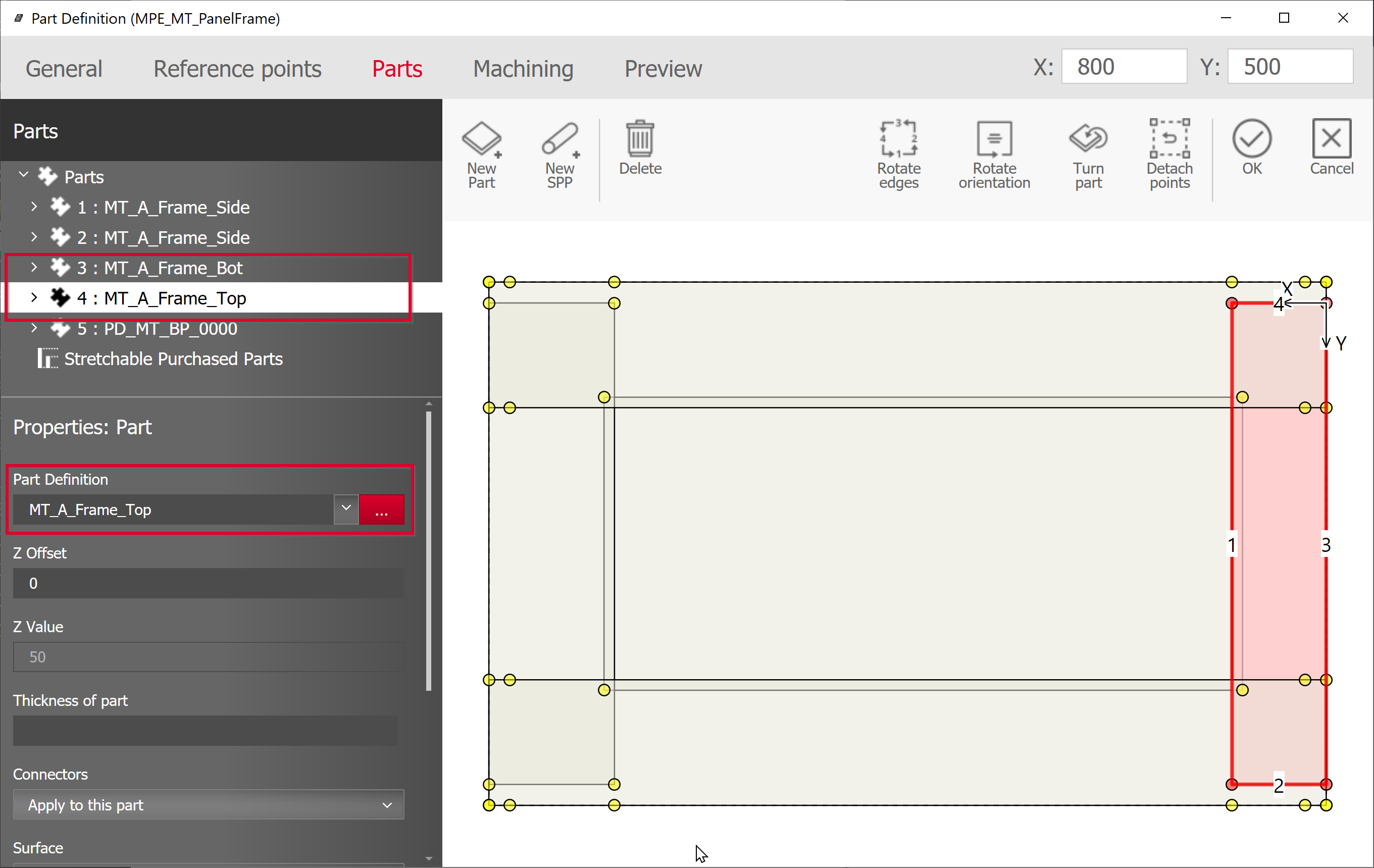
The multi-part element consists of four frame parts that form a rectangle, where the ends of the frame intersect.
The two shorter frame parts are assigned part definitions that contain the connection situations.
The connections are passed on to the two longer frame parts. The part definitions are called "MT_A_Frame_Top" and "MT_A_Frame_Bot".
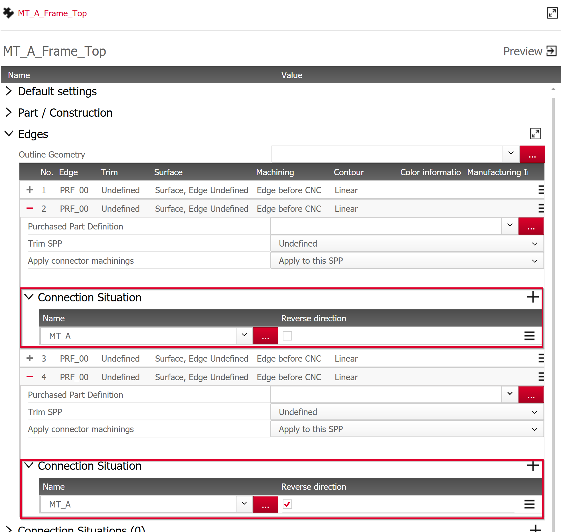
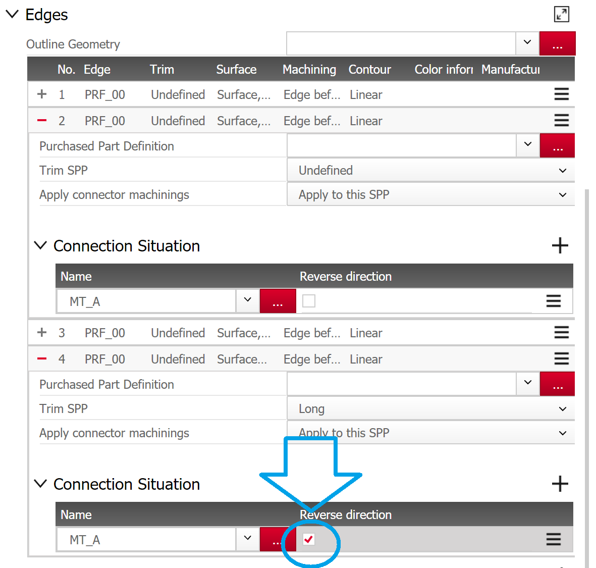
The connection situations are defined at edges 2 and 4 in the part definition. Both edges are assigned the connection situation "MT_A".
At edge 4, the checkbox "Reverse direction" is also checked in order to reuse the same connection situation by "mirroring".
Overview of the connection situation:
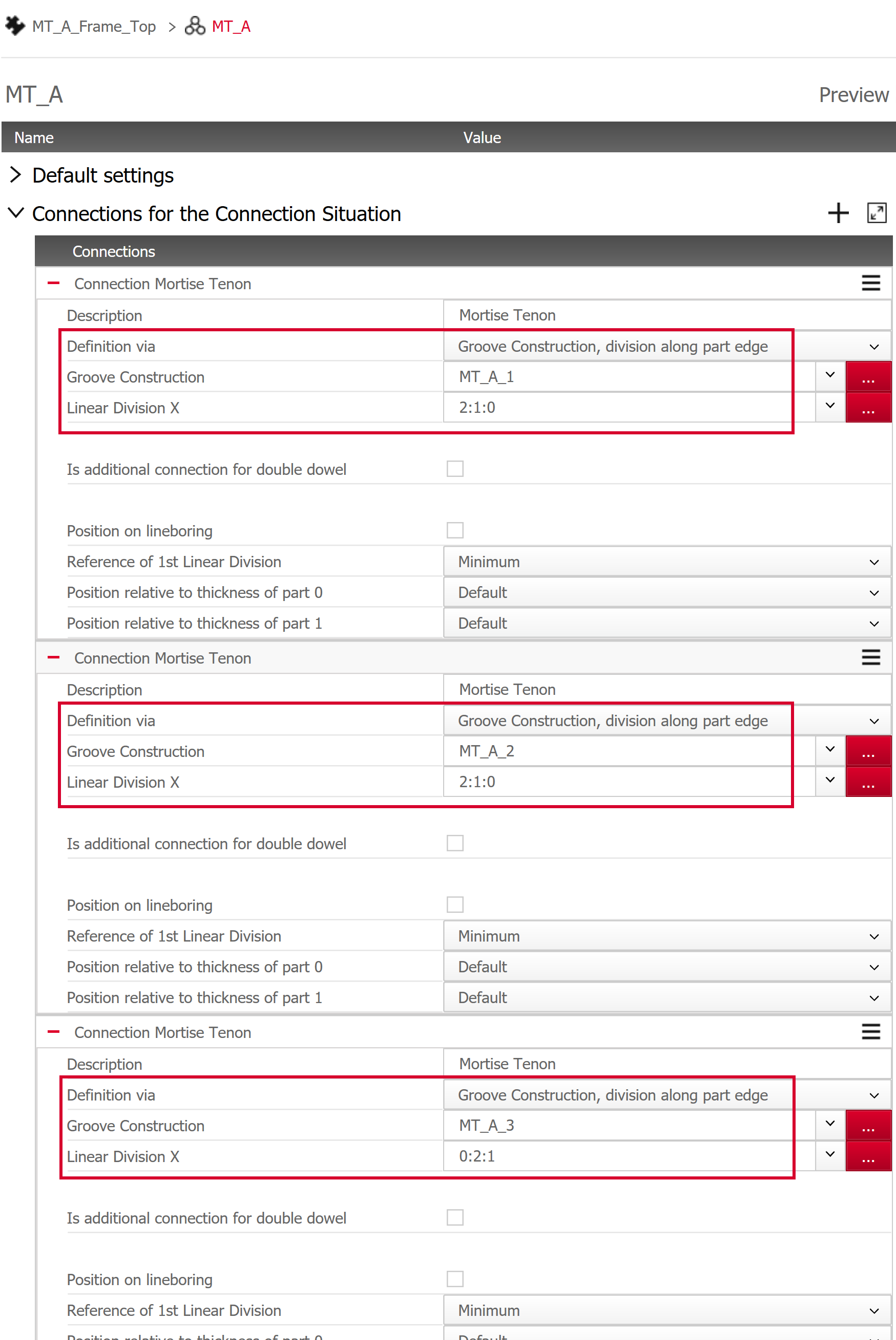
The connection situation MT_A consists of three different connections, which are configured as follows:
Connection 1: short tenon
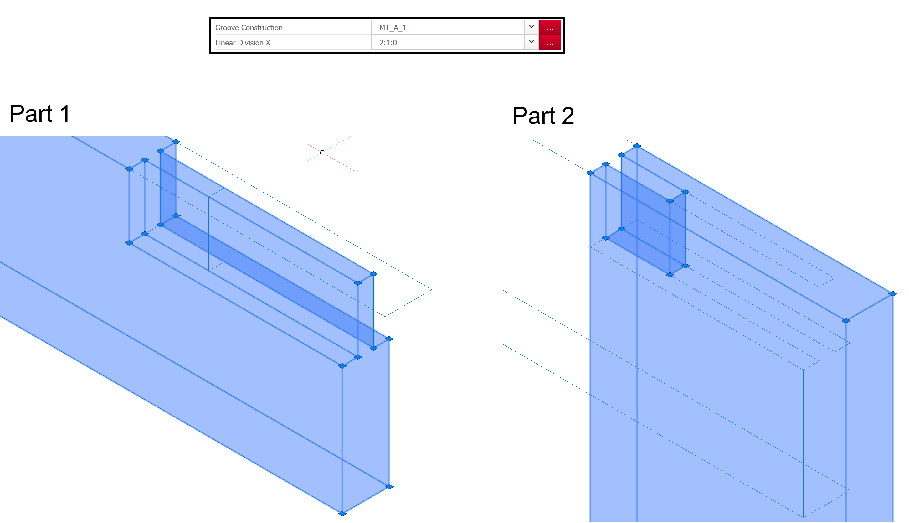
- Definition via = Groove construction, division along part edge
-
Groove construction = MT_A_1
The MT_A_1 principle has the following properties:- Linear division: 1:1:1
- Gap X1 = -($MT_Frame1W-$MT_TPOffset-$MT_Tenon1)/2
- Gap X2 = ($MT_Frame1W-$MT_TPOffset-$MT_Tenon1)/2
- Linear division X = 2:1:0
Connection 2: large cutout
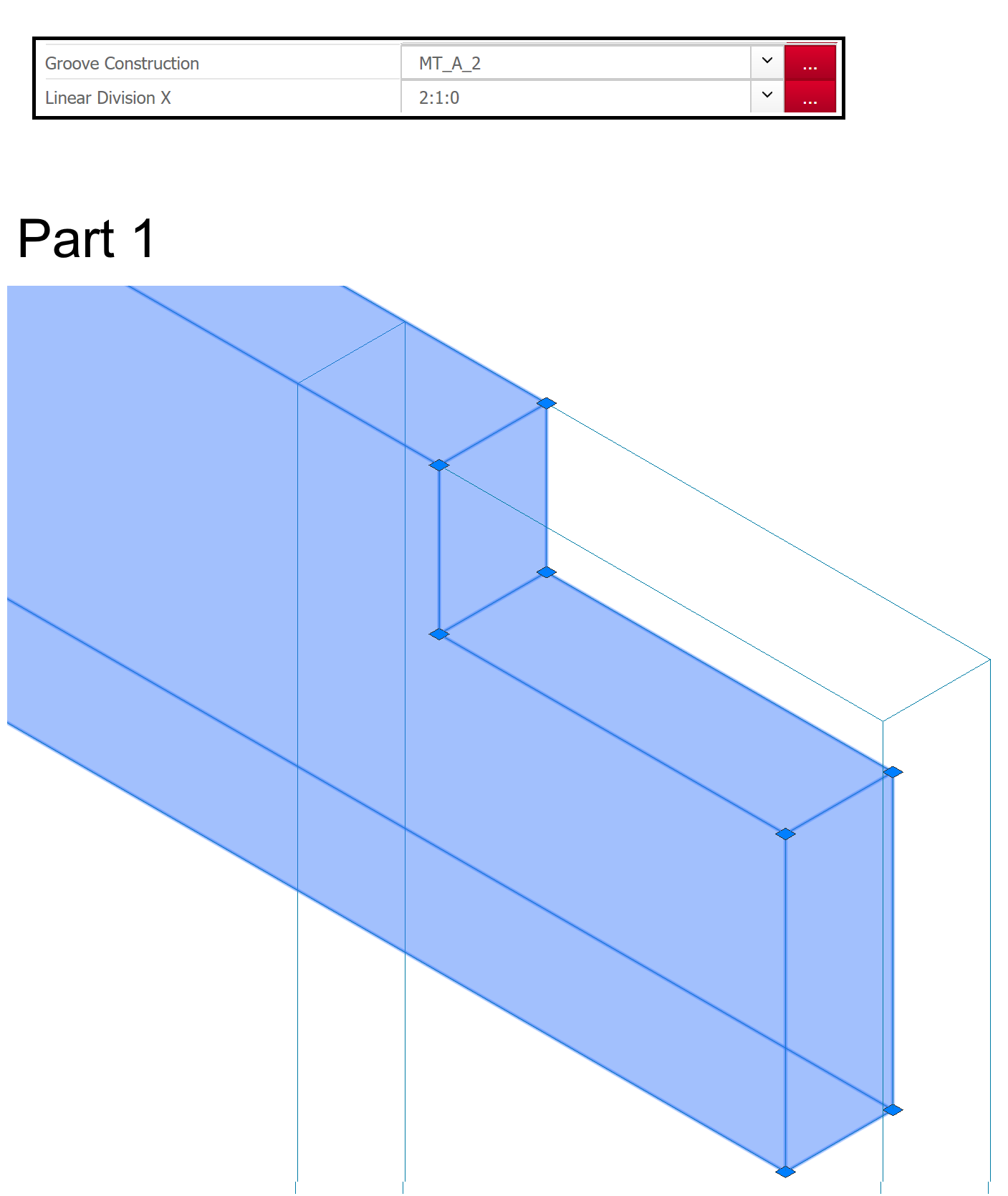
- Definition via = Groove construction, division along part edge
-
Groove construction = MT_A_2
The MT_A_2 principle has the following properties:- Linear division: 1:0
- Gap X2 = -$MT_Tenon1 + $MT_GrooveGap
- Linear division X = 2:1:0
Connection 3: long tenon
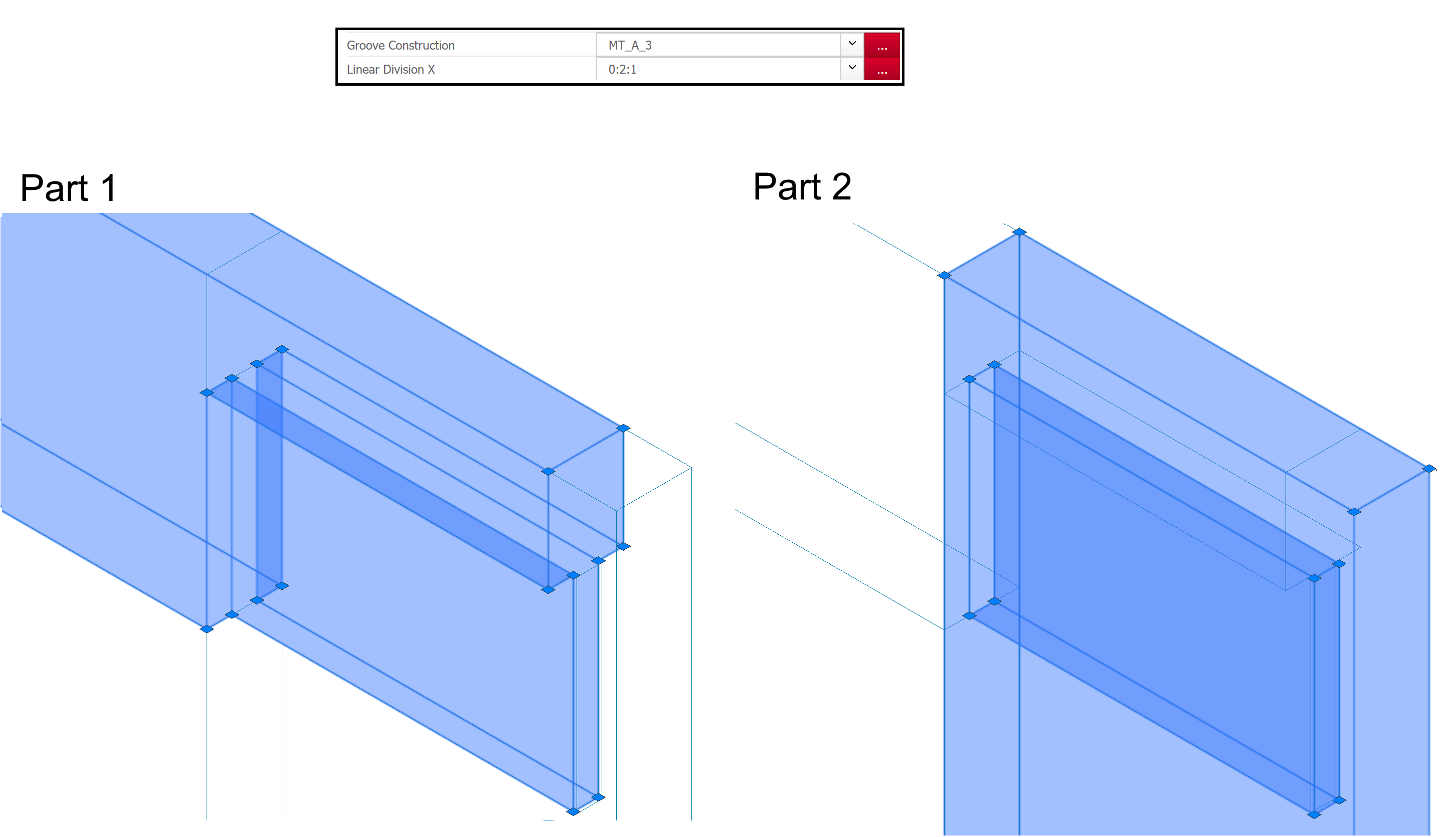
- Definition via = Groove construction, division along part edge
-
Groove construction = MT_A_3
The MT_A_3 principle has the following properties:- Linear division: 1:1:1
- Gap X1 = $MT_GrooveGap
- Linear division X = 0:2:1
Examples with different variable values:
Examples 1:
- $MT_Tenon1=30mm
- $MT_TPOffset=20mm
- $Frame1W=120mm
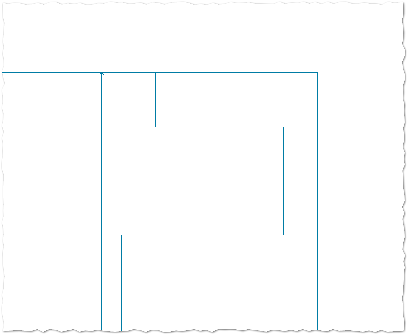
Examples 12
- $MT_Tenon1=10mm
- $MT_TPOffset=20mm:
- $Frame1W=120mm
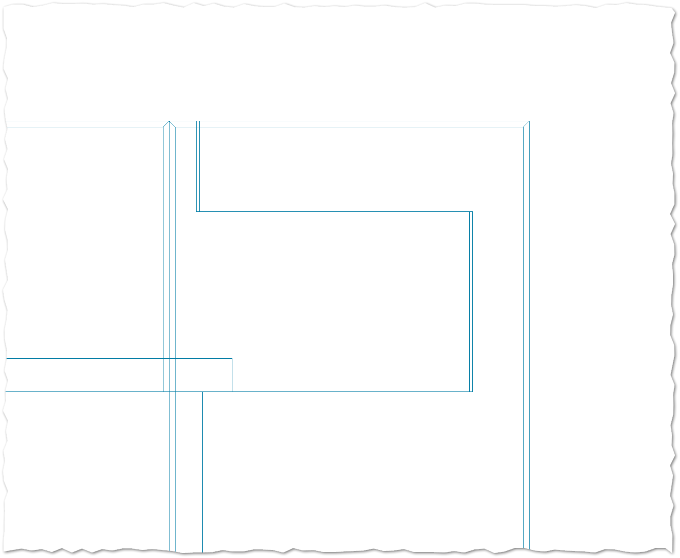
The shorter tenon is even shorter than in example 1.
Example 3:
- $MT_Tenon1=30mm
- $MT_TPOffset=40mm
- $Frame1W=120mm
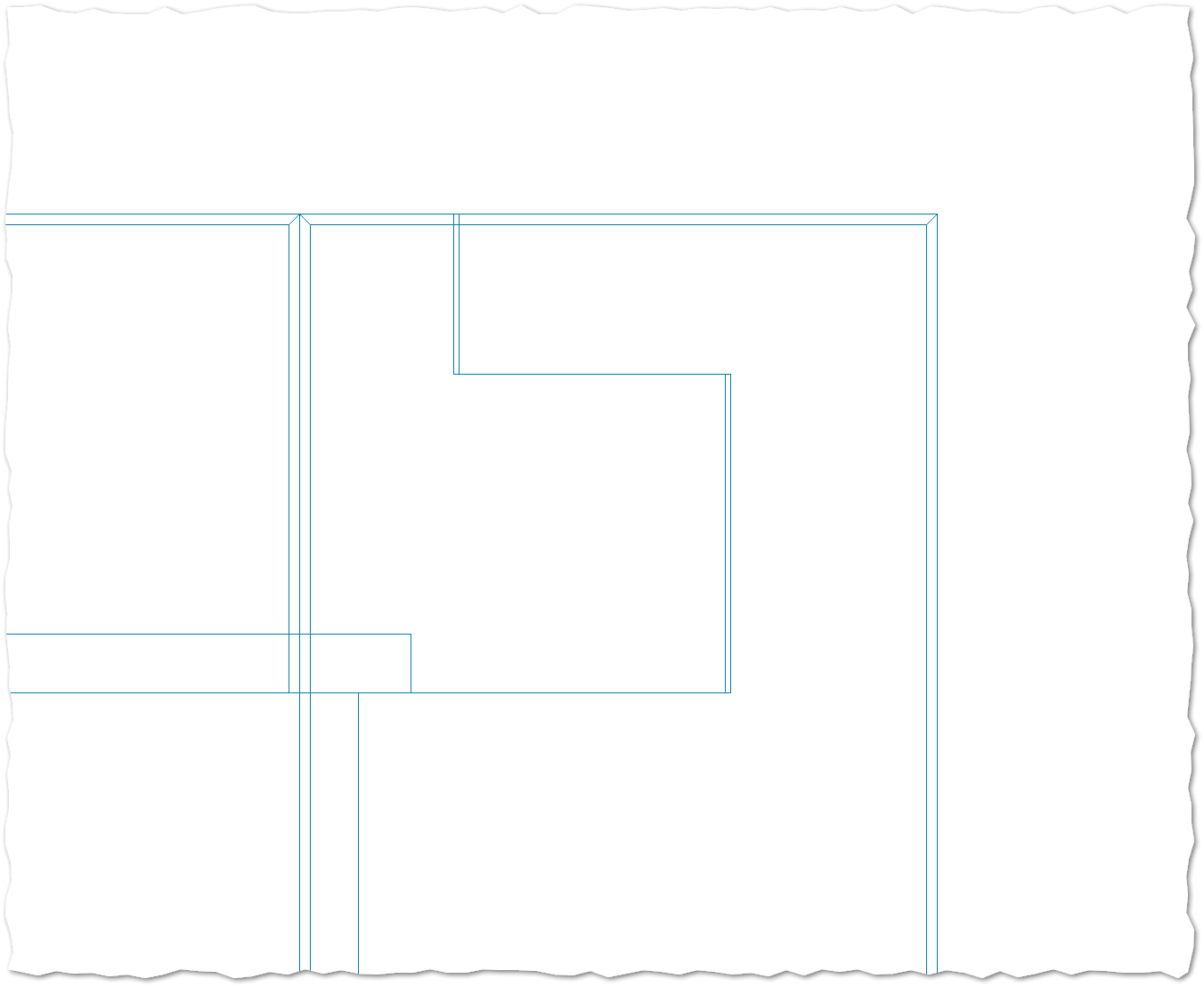
The distance between the long tenon and the edge of the multi-part element is greater than in example 1.
Example 4:
- $MT_Tenon1=30mm
- $MT_TPOffset=20mm
- $Frame1W=90mm
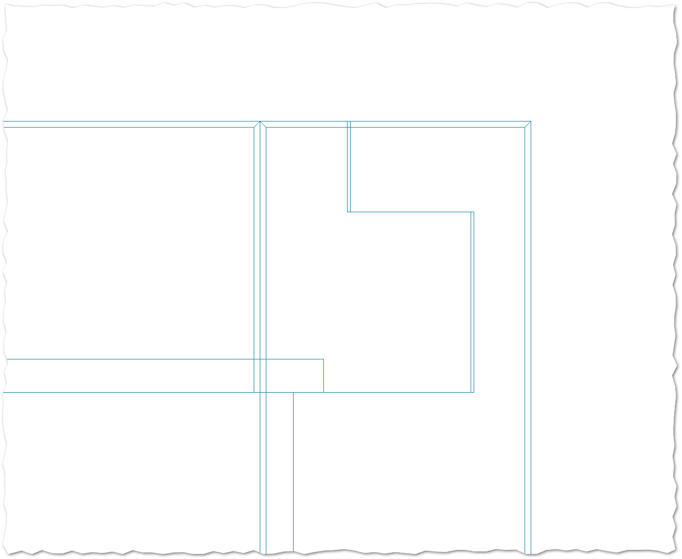
The right frame part is narrower compared to example 1. The long tenon shrinks accordingly.
Example: mortise-tenon connection with profile
Overview
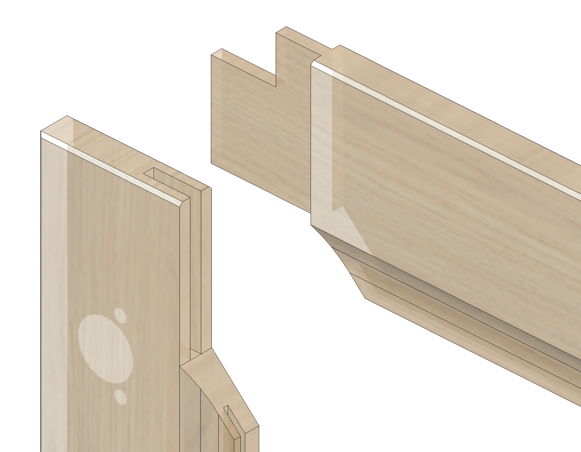
We want to create a frame door as a multi-part-element and connect the individual frame parts with mortise and tenon.The frame edges on the inside shall be given a profile.We proceed as follows:
- Use the Part Editor to create a frame construction consisting of four parts.The parts must intersect so that the desired cutouts can be created by means of groove constructions.
- Each part definition is given an outline geometry that takes into account the corresponding profile mitres, profile heights and frame widths.
- In each frame part definition, assign connection situations to the edges that are to create a mortise&tenon joint.
- The assigned connection situation has several connections of the type "Groove construction, division along part edge".This makes it possible...
- to divide the mortise&tenon connection into sections
- to assign a corresponding groove construction per section, each of which generates a portion of the mortise&tenon connection.
Info: The orientation of an edge connection (in the part definition) can be "reversed" if necessary to "mirror" the orientation of machinings on the left/right.This allows you to reuse the same connection.
- Adjust the groove construction principles to take into account the profile dimensions.
Data set-up in detail
The article called "SW_MT_Profile" is a kitchen cabinet with a double door.Both leaves of the double door have the same frame construction.The frame parts have a particular profile and are connected with mortise and tenon.
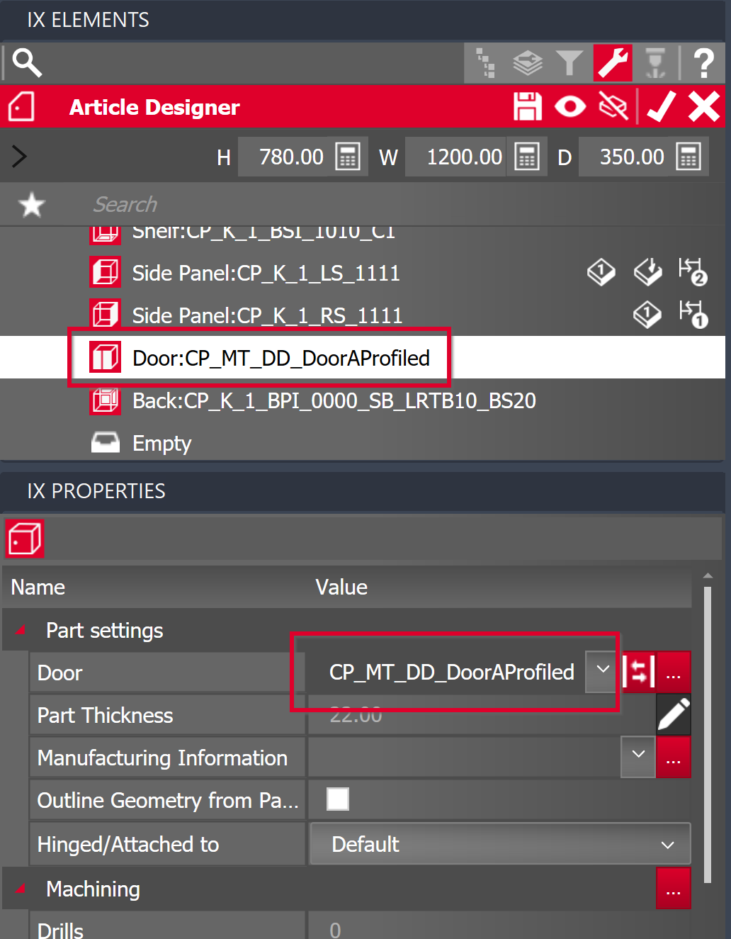
The cabinet door is assigned the construction principle "CP_MT_DD_DoorAProfiled".
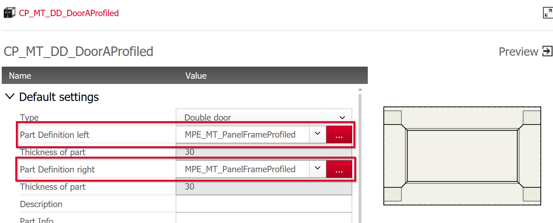
In the construction principle, the part "MPE_MT_PanelFrameProfiled" is assigned to the left and right door leaves. Here we deal with a multi-part element.
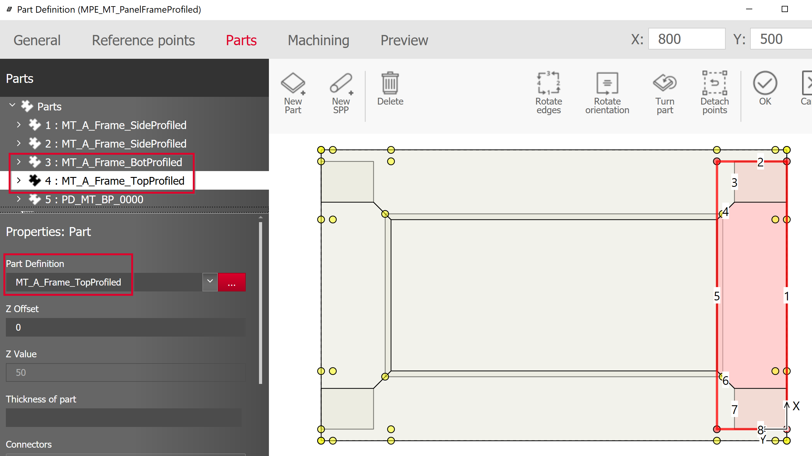
The multi-part element consists of four frame parts that form a rectangle, where the ends of the frame intersect.
The two shorter frame parts are assigned part definitions that contain the connection situations.
The connections are passed on to the two longer frame parts. The part definitions are called "MT_A_Frame_TopProfiled" and "MT_A_Frame_BotProfiled".
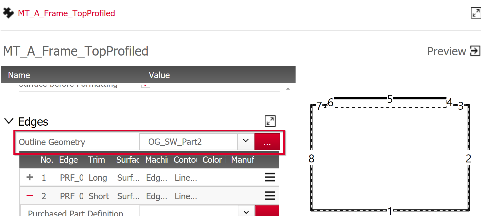
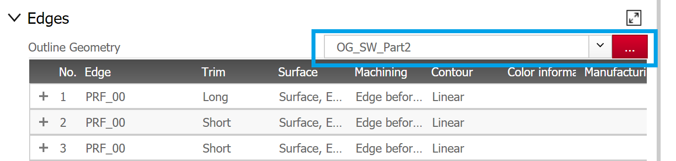
Both part definitions are assigned the outline geometry "OG_SW_Part2".
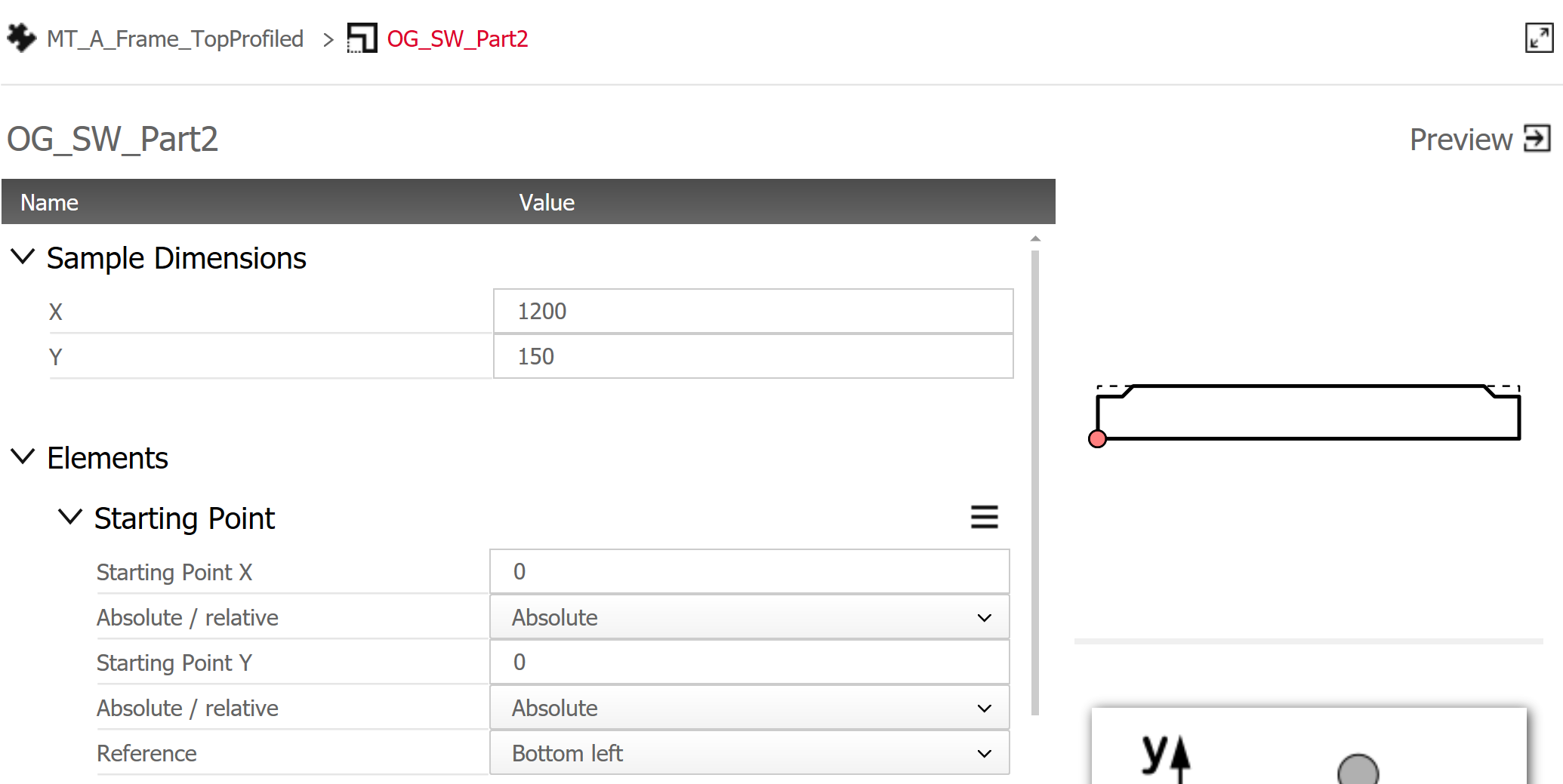
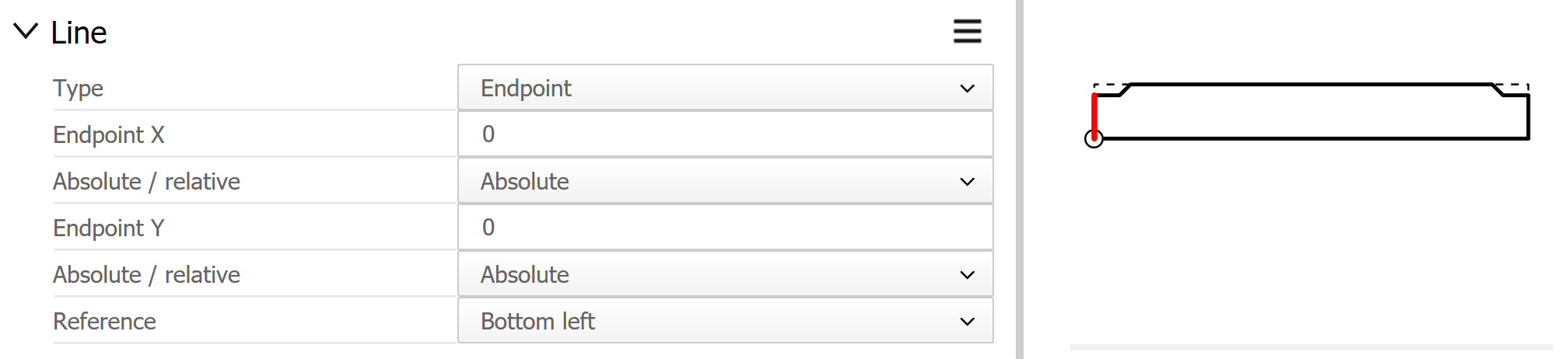
Some segments in the outline geometry principle are influenced by variables, e.g. to take into account the maximum profile thickness.
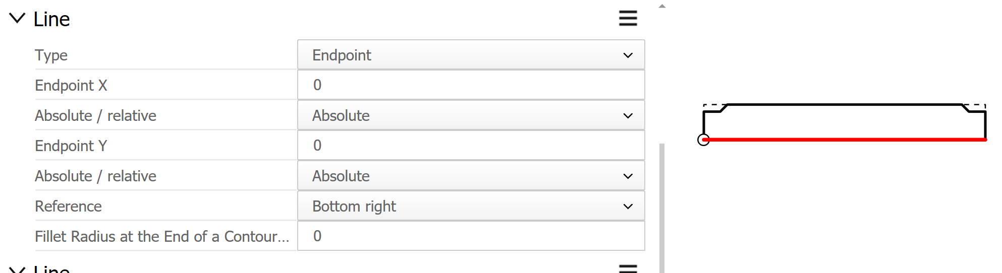
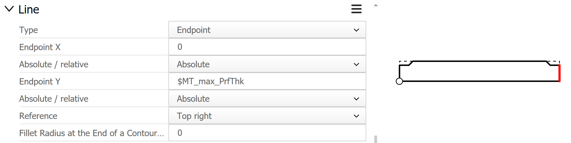
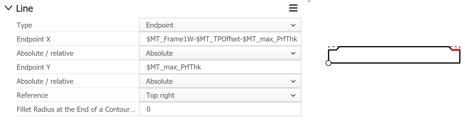
List of segments in the outline geometry principle (sorted counterclockwise):
| Starting Point X | 0 |
| Starting Point Y | 0 |
| Reference | Bottom left |
| Endpoint X | 0 |
| Endpoint Y | 0 |
| Reference | Bottom right |
| Screenshot |
|
| Endpoint X | 0 |
| Endpoint Y | $MT_max_PrfThk |
| Reference | Top right |
| Screenshot |
|
| Endpoint X | $MT_Frame1W-$MT_TPOffset-$MT_max_PrfThk |
| Endpoint Y | $MT_max_PrfThk |
| Reference | Top right |
| Screenshot |
|
| Endpoint X | $MT_Frame1W-$MT_TPOffset |
| Endpoint Y | 0 |
| Reference | Top right |
| Screenshot |
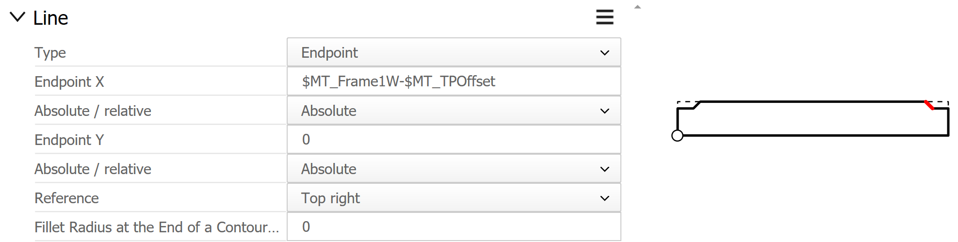
|
| Endpoint X | $MT_Frame1W-$MT_TPOffset |
| Endpoint Y | 0 |
| Reference | Top left |
| Screenshot |
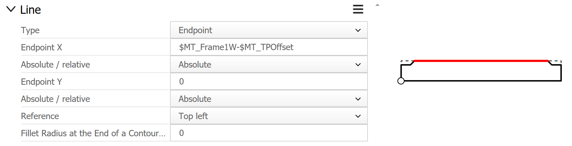
|
| Endpoint X | $MT_Frame1W-$MT_max_PrfThk-$MT_TPOffset |
| Endpoint Y | $MT_max_PrfThk |
| Reference | Top left |
| Screenshot |
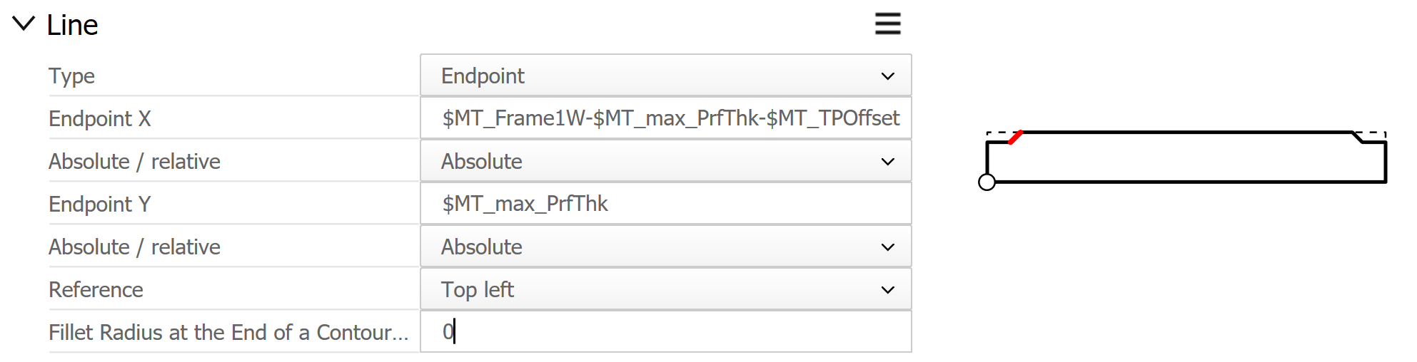
|
| Endpoint X | 0 |
| Endpoint Y | $MT_max_PrfThk |
| Reference | Top left |
| Screenshot |
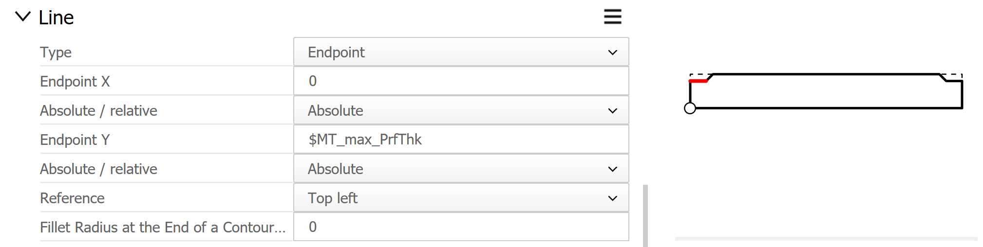
|
| Endpoint X | 0 |
| Endpoint Y | 0 |
| Reference | Bottom left |
| Screenshot |
|
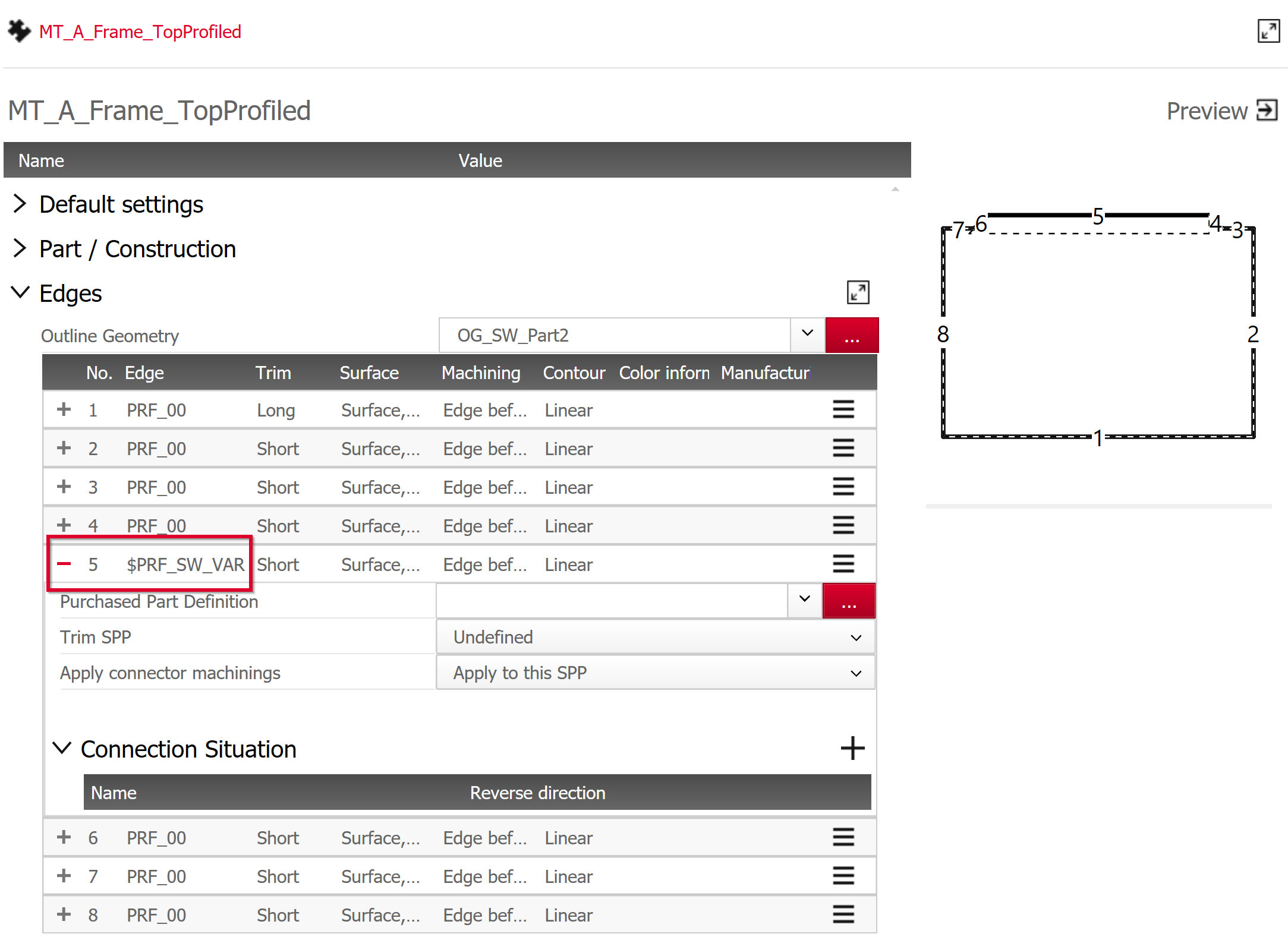
Now let's take another look at the part definition.At the edge, which points inwards in the frame construction, a profile geometry is assigned via variable.The variable is called "$PRF_SW_VAR" in order to be able to assign a different geometry afterwards.
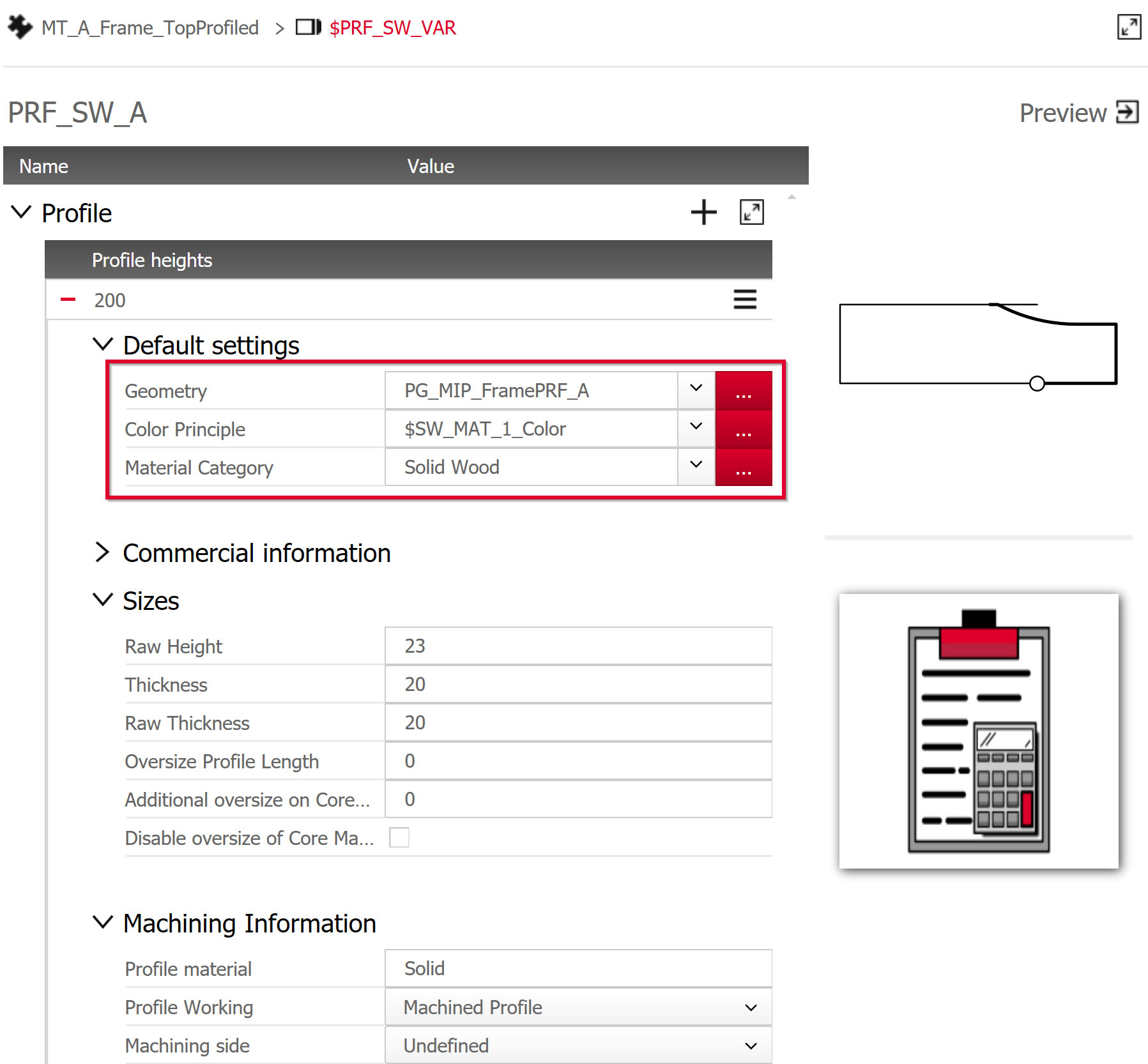
The profile behind the variable is initially "PRF_SW_A".
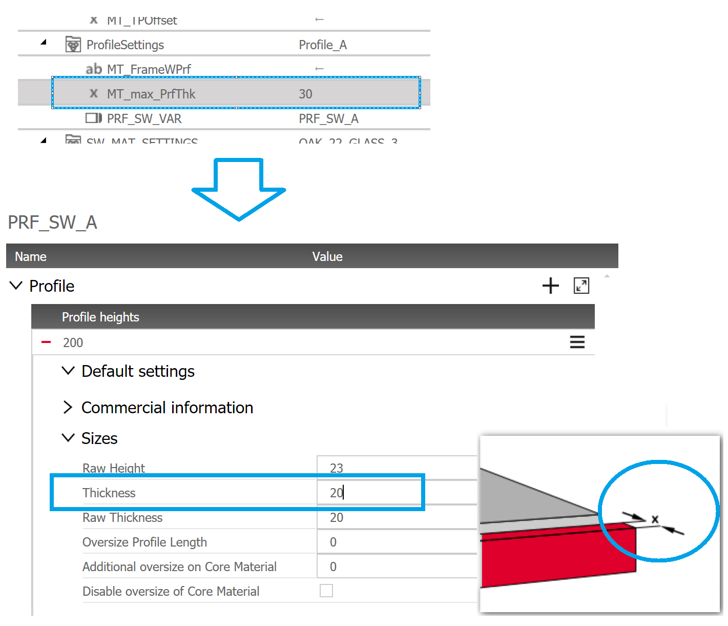
Info: The variable $MT_max_PrfThk is related to the "profile thickness" used.The variable determines how large the mitre must be in the part contour so that the profile "fits" in.In any case, the value of the variable must always be greater than or equal to the profile thickness used.
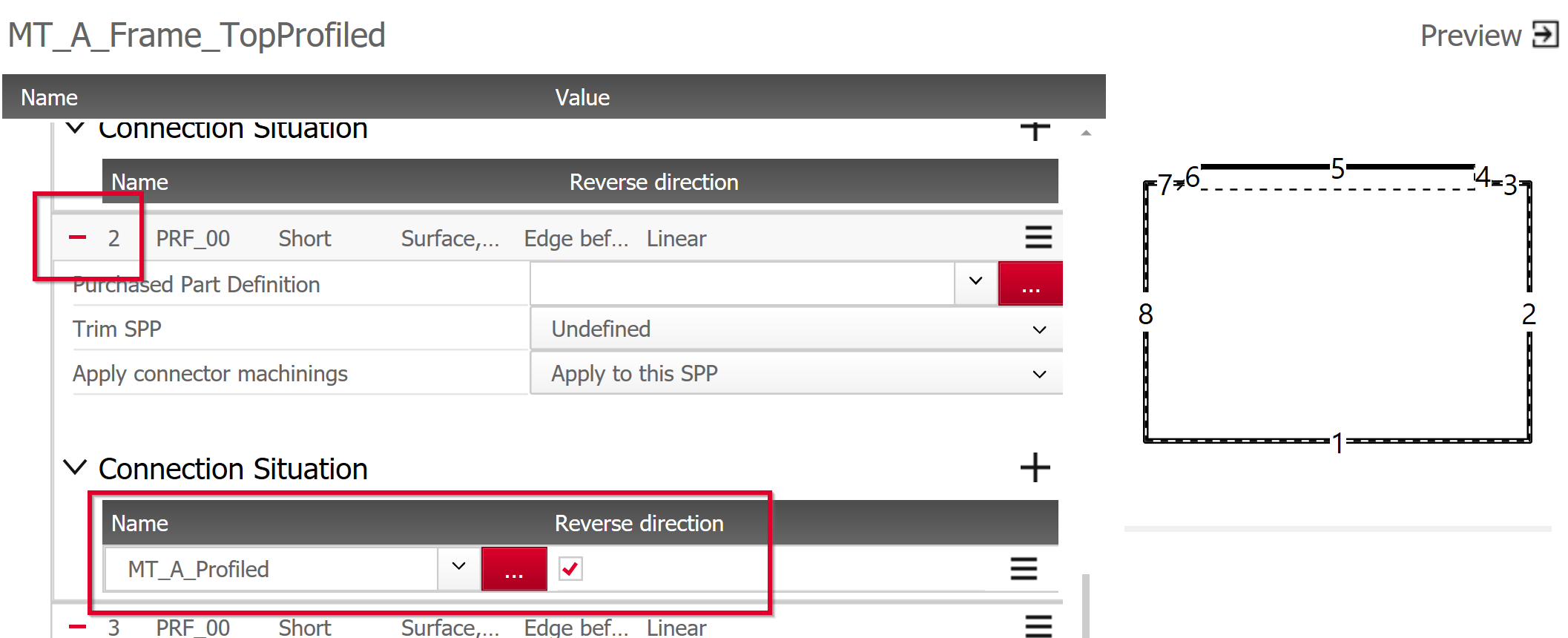
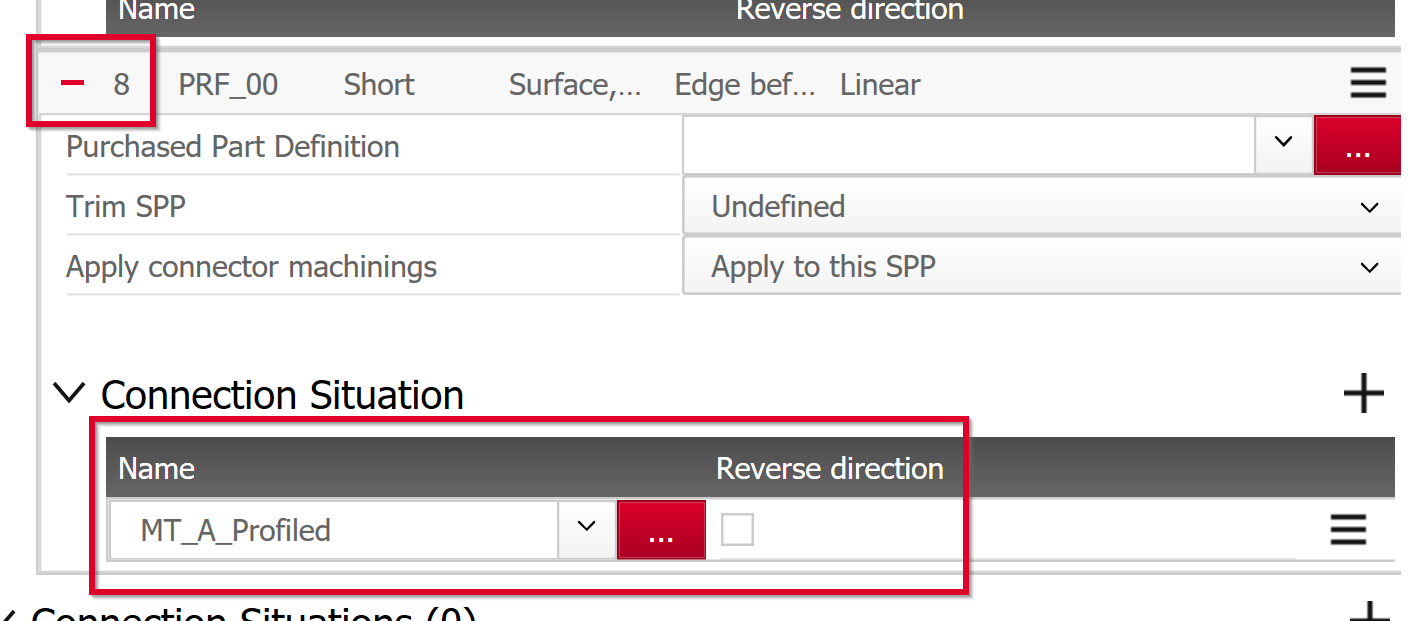
The connection situations are defined at edges 2 and 8 in the part definition.Both edges are assigned the connection situation "MT_A_Profiled".
At edge 8, the checkbox "Reverse direction" is also ticked in order to reuse the same connection situation by "mirroring".
Overview of the connection situation "MT_A_Profiled":
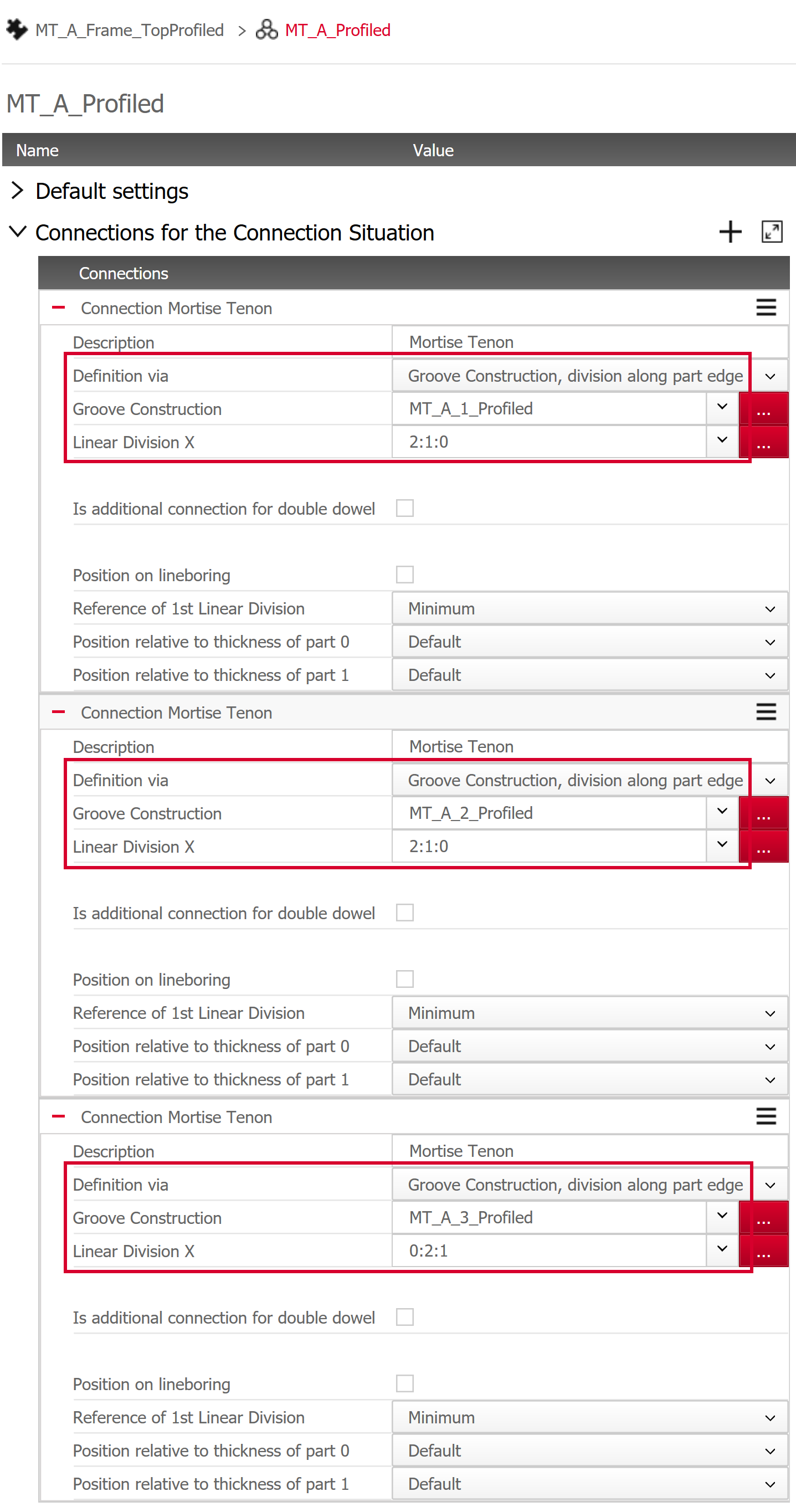
The connection situation MT_A_Profiled consists of three different connections, which are configured as follows:
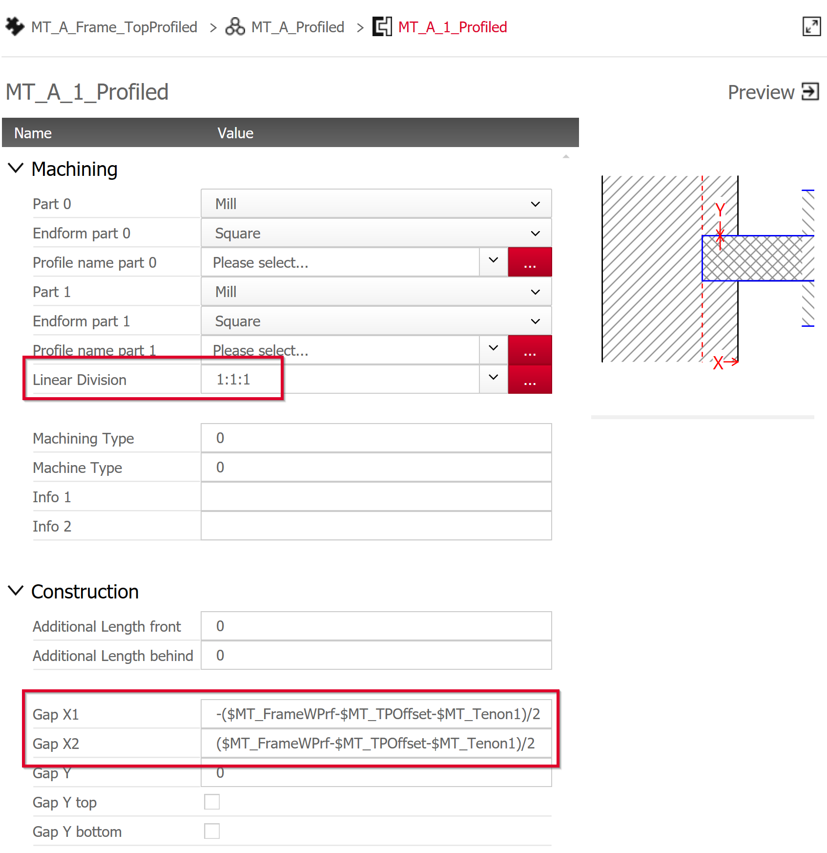
Connection 1:
- Definition via = Groove construction, division along part edge
-
Groove construction = MT_A_1_Profiled
The principle MT_A_1_Profiled has the following properties:- Linear division: 1:1:1
- Gap X1 = -($MT_FrameWPrf-$MT_TPOffset-$MT_Tenon1)/2
- Gap X2 = ($MT_FrameWPrf-$MT_TPOffset-$MT_Tenon1)/2
- Linear division X = 2:1:0
Info: Here, the variable value of $MT_FrameWPrf consists of a formula, which in turn refers to variables.The formula is "$MT_Frame1W-$MT_max_PrfThk".This means that the profile thickness is subtracted from the frame thickness.The profile thickness is set manually using the variable "$MT_max_PrfThk" – it is not automatically obtained from the construction.
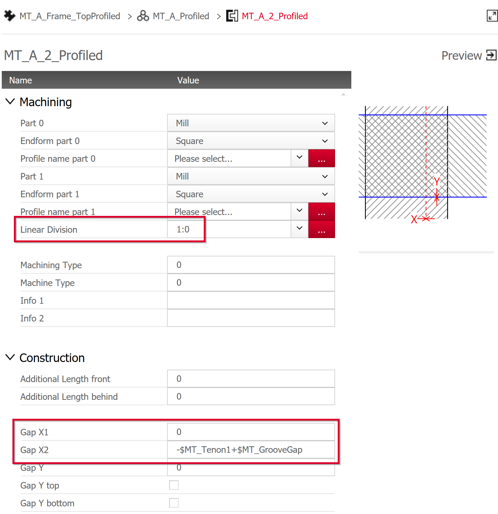
Connection 2:
- Definition via = Groove construction, division along part edge
-
Groove construction = MT_A_2_Profiled
The principle MT_A_2_Profiled has the following properties:- Linear division: 1:0
- Gap X2 = -$MT_Tenon1+$MT_GrooveGap
- Linear division X = 2:1:0
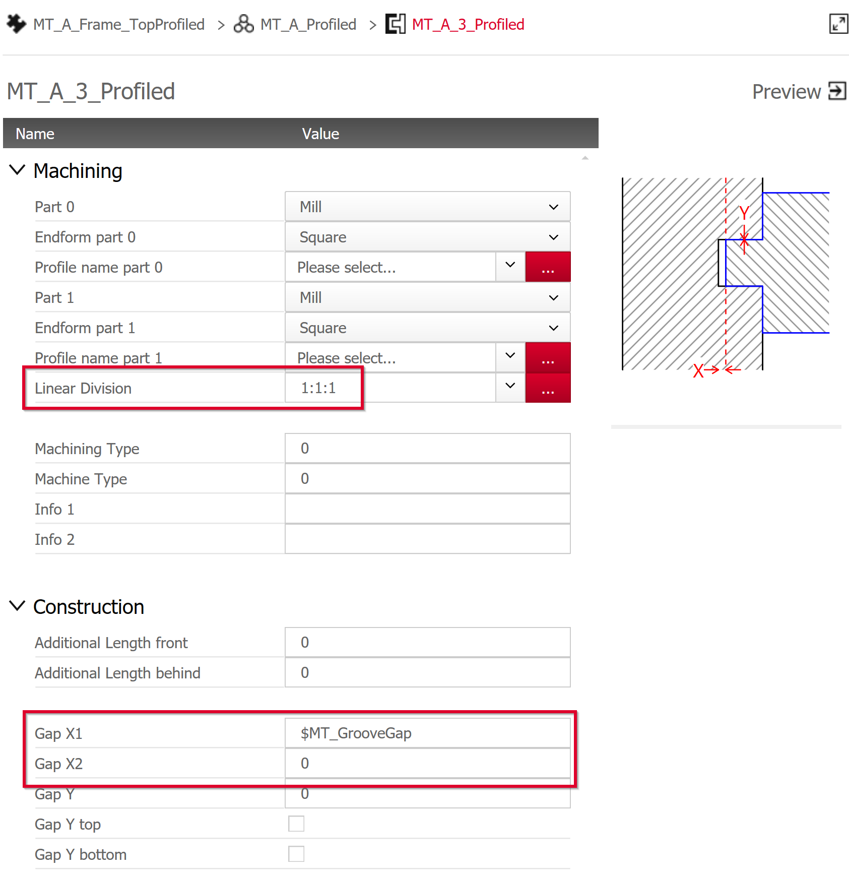
Connection 3:
- Definition via = Groove construction, division along part edge
-
Groove construction = MT_A_3_Profiled
The principle MT_A_3_Profiled has the following properties:- Linear division: 1:1:1
- Gap X1 = $MT_GrooveGap
- Linear division X = 0:2:1
Examples with different variable values:
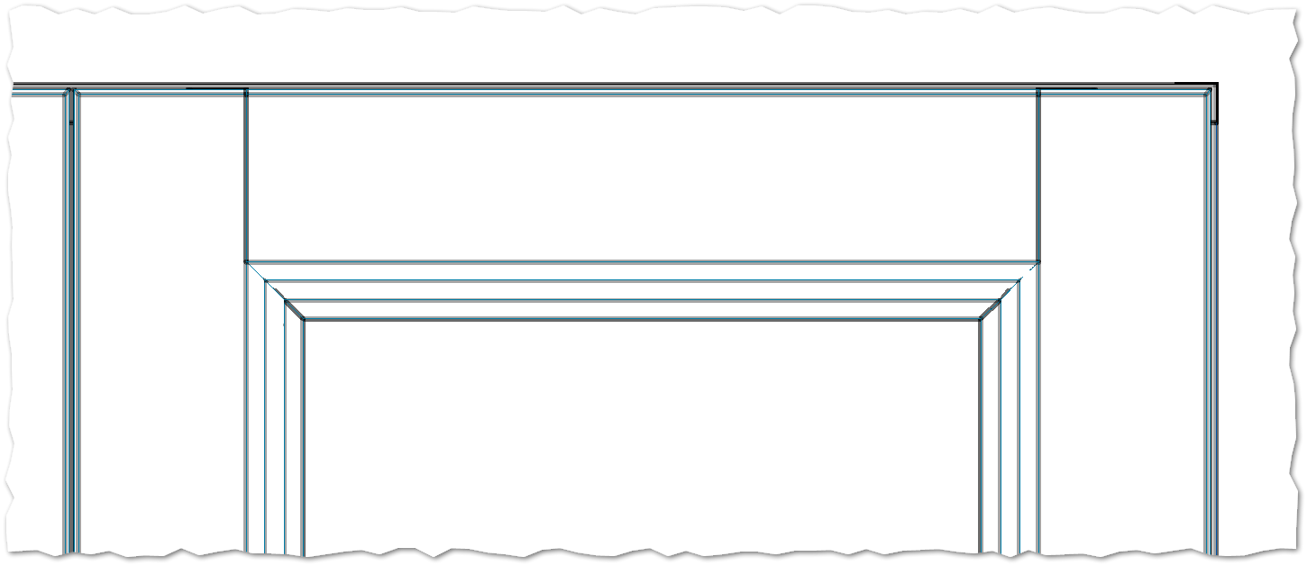
Example for $MT_max_PrfThk = 30 (= thickness of the profile used):
A tenon corner and profile corner meet at the same point because the variable value corresponds to the profile thickness.
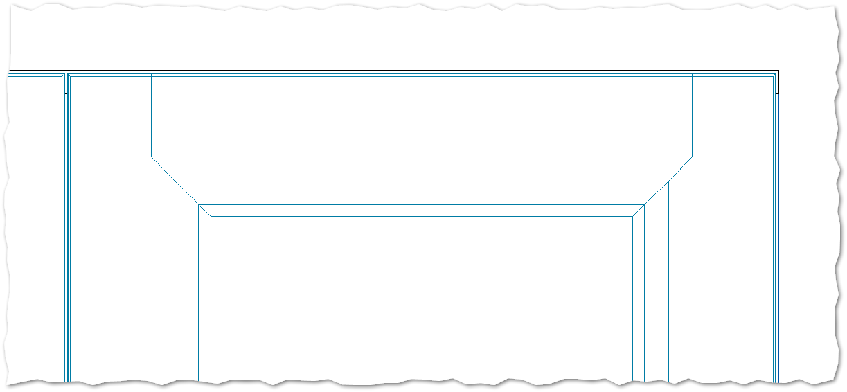
Example for $MT_max_PrfThk = 50 (> thickness of the profile used):
No tenon corner meets a profile corner because the variable value is greater than the profile thickness.
Example: Box Joint
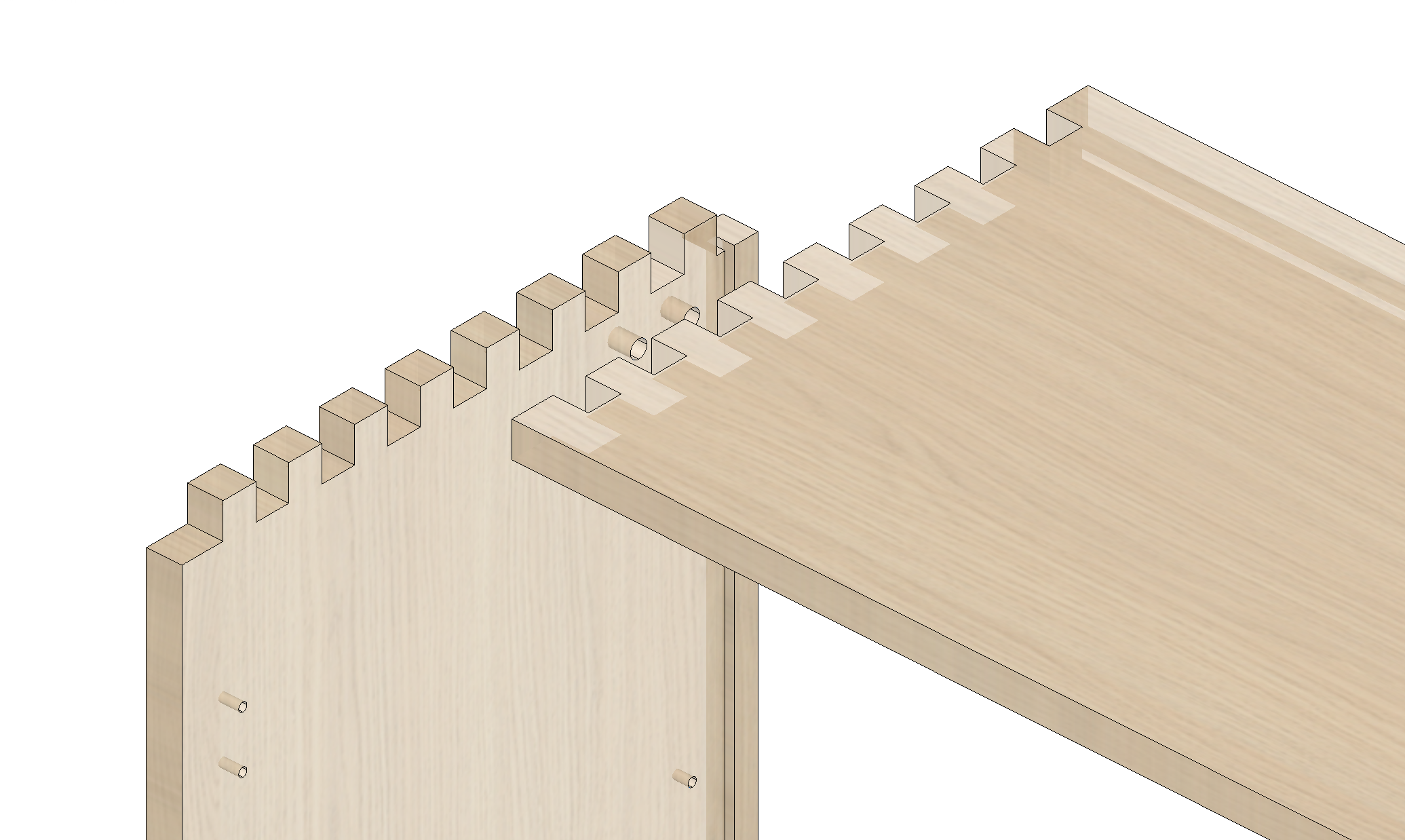
Overview
We want to connect the sides of a carcass using box joints. We proceed as follows:
- In the part definitions for the top and bottom shelf, create a connection situation of the type "Groove construction, division along part edge" at respective edges.
-
Enter the desired box joint division in the linear division field. Choose one of the following approaches for the formula:
-
Define box joints by the desired number of joints:
Here, the desired number of joints is defined. The joints are evenly distributed across the part width (imos system variable 'Y'). The actual joint size depends on the part width.
Formula example: n * ( Y / $BoxJoint_Count ) mm : 1
-
Define box joints by the desired joint size:
Here, the desired size of the joints is defined. The number of joints is determined by the part width. Only the first and last joints differ in size from the other joints, as the remaining part width is accounted for. This remainder is defined in the formula with "+1".
Formula example: 10mm + 1 : n * 20mm : 20mm : n * 20mm : 10mm + 1
- 10mm+1 -> Ensures that the joints at the ends are never <10mm.
- n*20mm:20mm:n*20mm (instead of just n*20) -> Ensures that there is always an odd number of joints so that the joints of both parts can interlock. If the number is even, problems may occur.
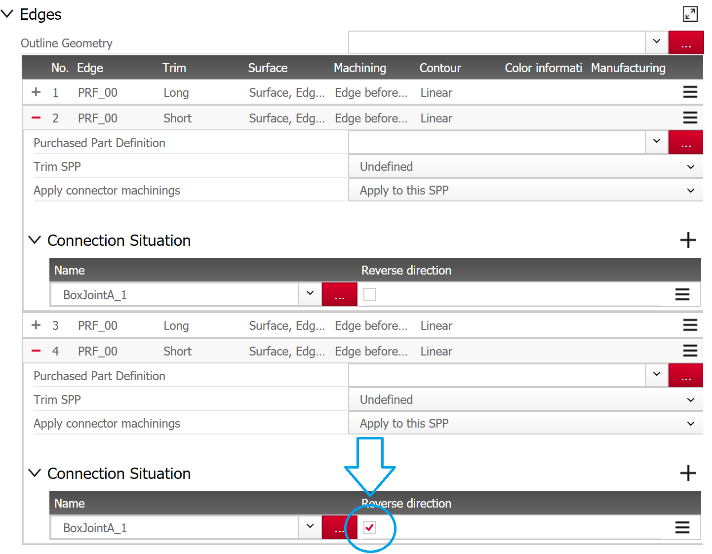
Note: The connection direction must be "reversed" at one edge in the part definition, so that the orientation of the machining on the left/right is "mirrored".
-
-
The same procedure is followed for the part definitions on the left and right sides of the carcass. However, the linear division in the connection must be adjusted so that a complementary part is created.
For this, the same linear division is used as for the top shelf/bottom shelf, but with a "to zero" division at the beginning and at the end:
0:<desired division>:0
Example: 0:10mm+1:n*20mm:20mm:n*20mm:10mm+1:0
Data Set-Up in Detail
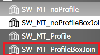
The article called "SW_MT_ProfileBoxJoin" is a kitchen cabinet. The sides of the carcass are connected using box joints.
In the following, we will take a closer look at the connection between the right side of the carcass and the top shelf.
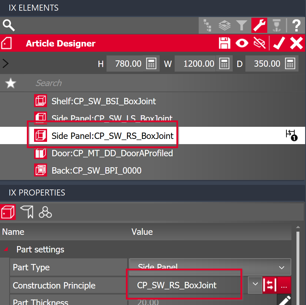
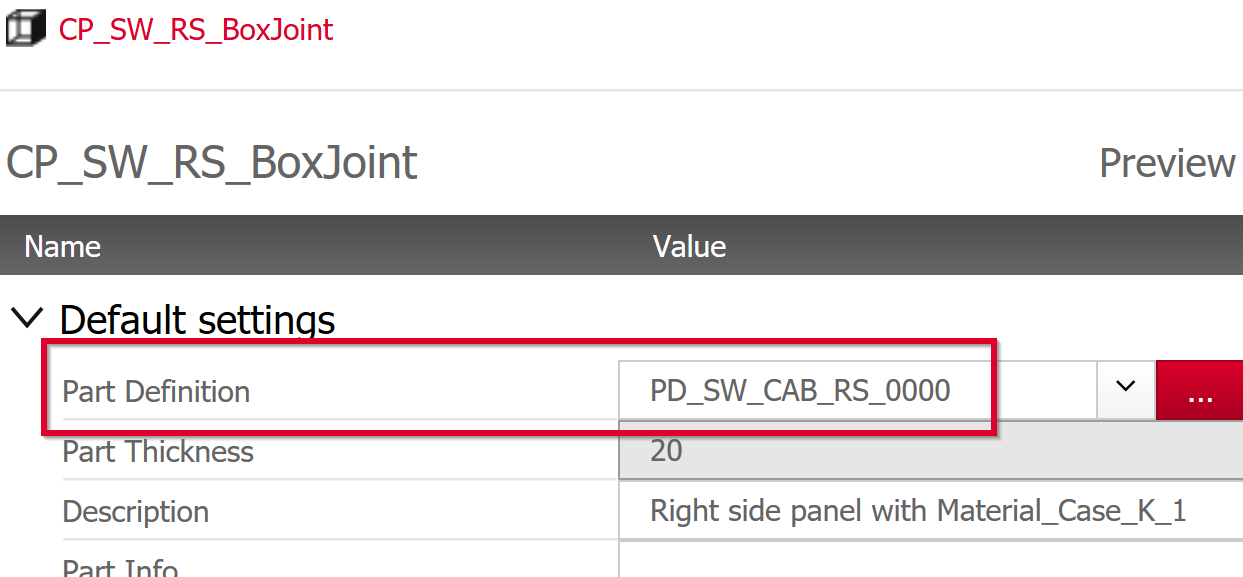
The right side of the carcass is assigned the construction principle "CP_SW_RS_BoxJoint", which contains the part definition "PD_SW_CAB_RS_0000".
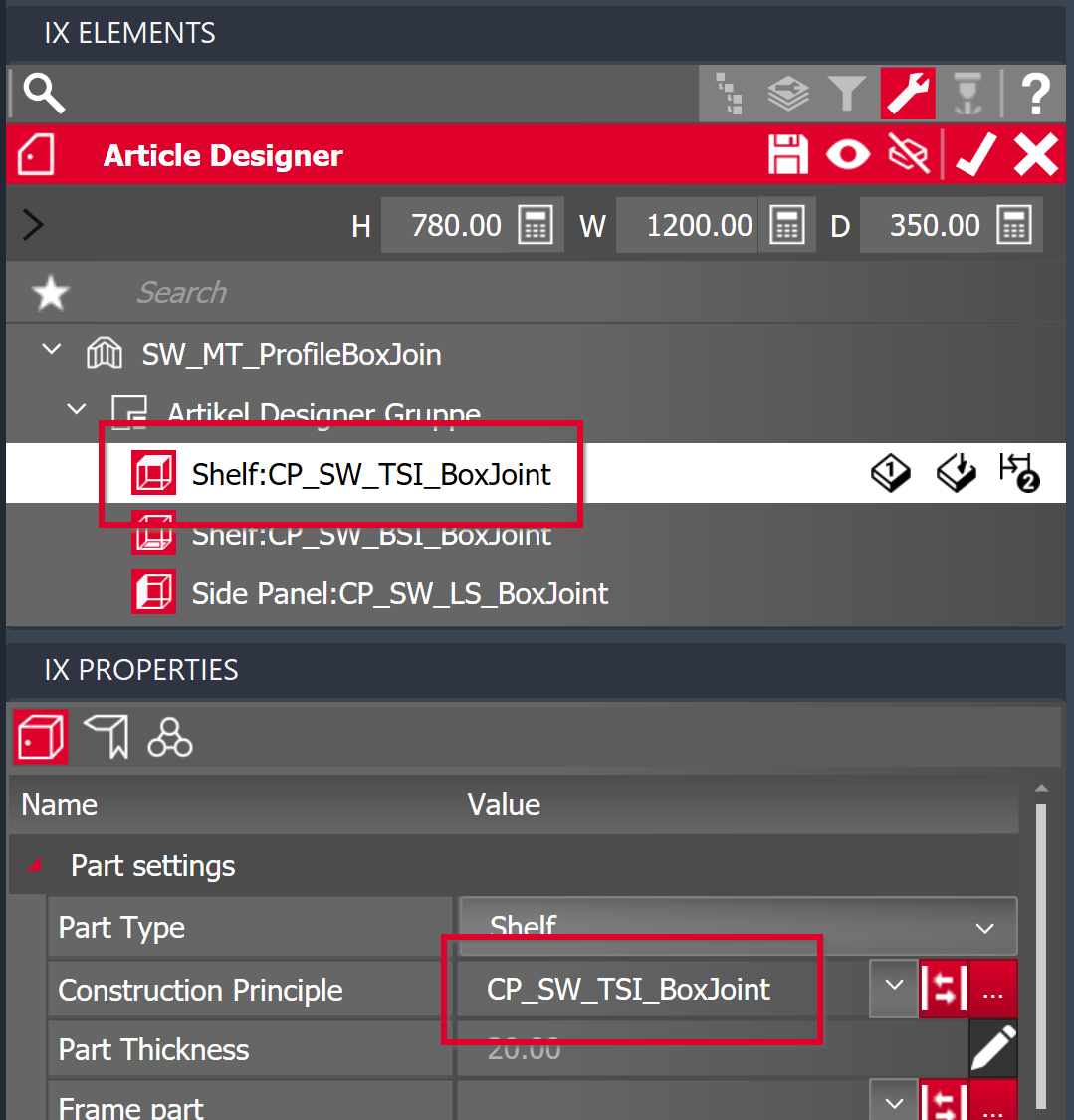
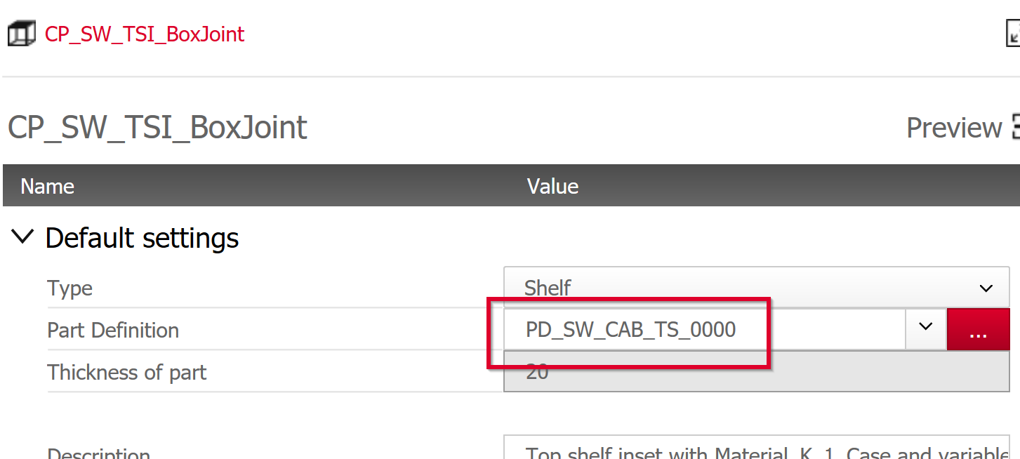
The top shelf is assigned the construction principle "CP_SW_TSI_BoxJoint", which contains the part definition "PD_SW_CAB_TS_0000".
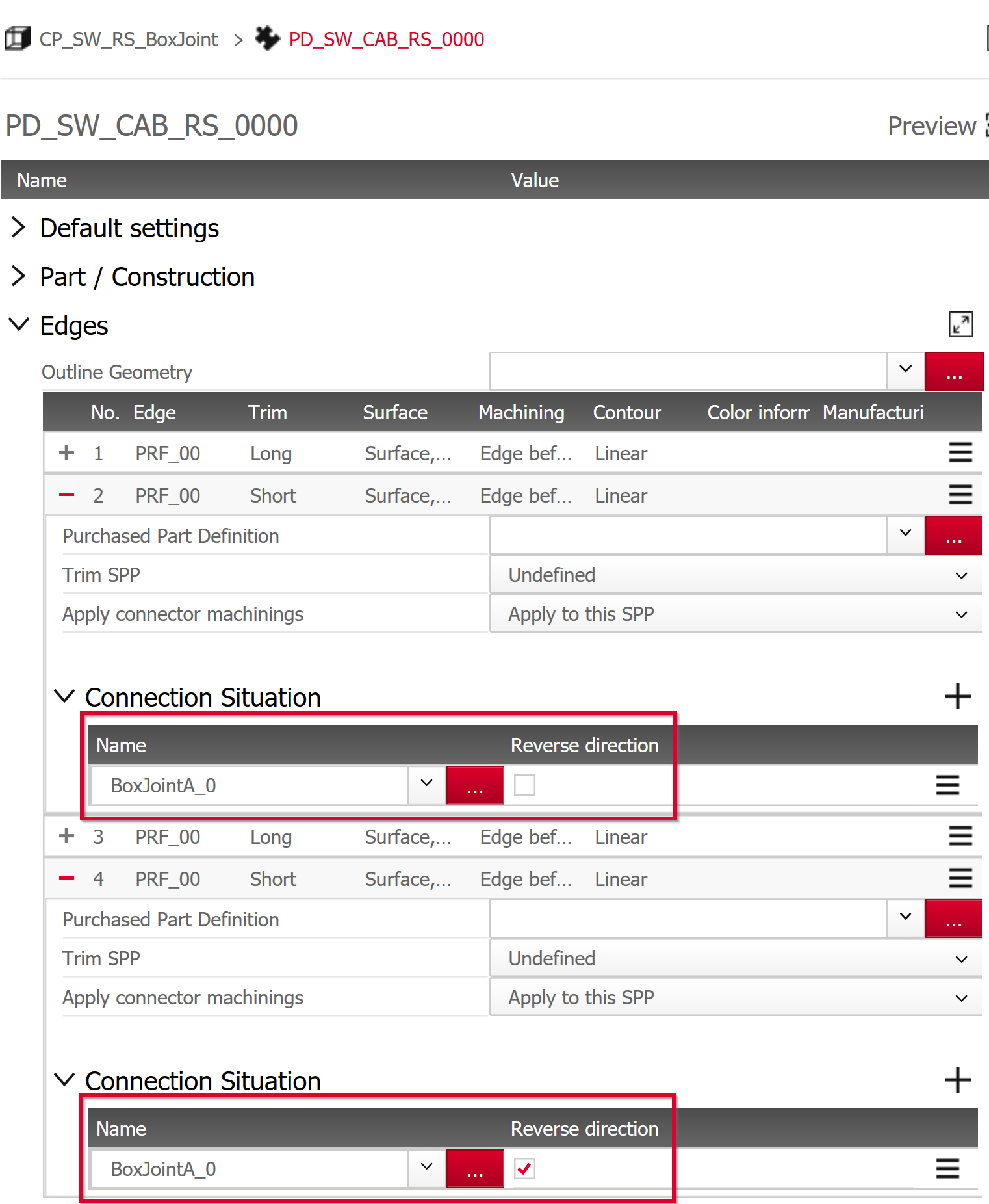
In the part definition of the right carcass side, the connection situation "BoxJointA_0" is assigned at edges 2 and 4.
At edge 4, the checkbox "Reverse direction" is also checked in order to reuse the same connection situation by "mirroring".
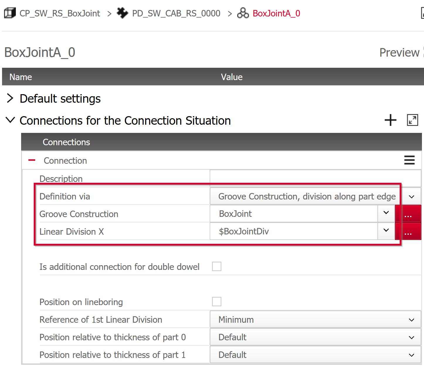
"BoxJointA_0" consists of a connection defined as follows:
- Definition via = Groove construction, division along part edge
- Groove construction = BoxJoint
- Linear division X = $BoxJointDiv
In the linear division, a variable is used in order to be able to quickly change the joint widths later on via the variable dialog.
Here: $BoxJointDiv = 10mm+1:n*20mm:20mm:n*20mm:10mm+1
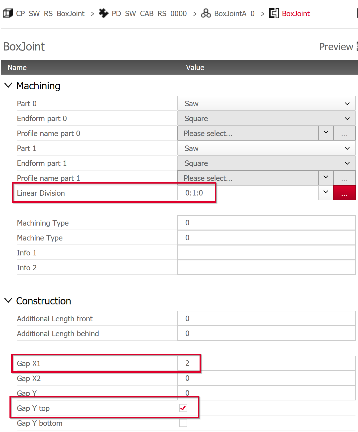
The groove construction "BoxJoint" has the following properties:
- Linear division = 0:1:0
- Gap X1 = 2
The right side is now configured. Let's now look at the top shelf.
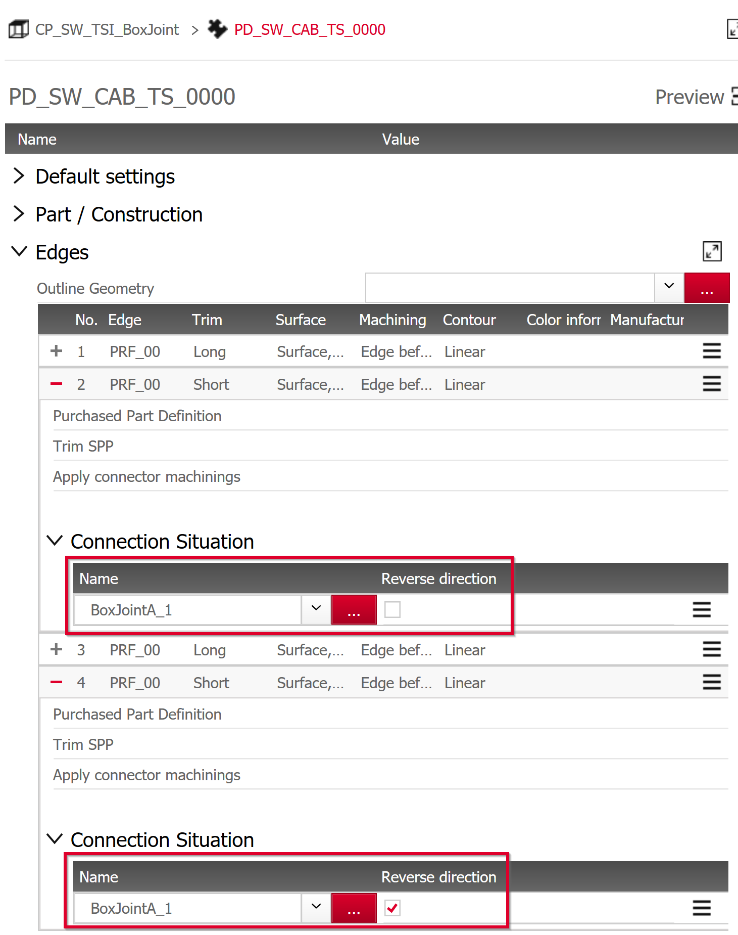
In the part definition of the top shelf, the connection situation "BoxJointA_1" is assigned at edges 2 and 4.
At edge 4, the checkbox "Reverse direction" is also checked in order to reuse the same connection situation by "mirroring".
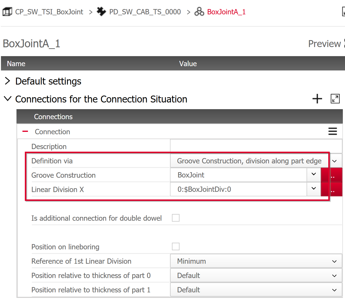
"BoxJointA_1" consists of a connection defined as follows:
- Definition via = Groove construction, division along part edge
- Groove construction = BoxJoint
- Linear division X = 0:$BoxJointDiv:0
The same groove construction is used as in "BoxJointA_0". However, in order for the joints of both parts to interlock, the linear division is formulated in a complementary way to "BoxJointA_0", i.e., it has a "to zero division" at the beginning and end of the formula.
Example of different values for variable $BoxJointDiv:
Example1: $BoxJointDiv = 10mm+1:n*20mm:20mm:n*20mm:10mm+1
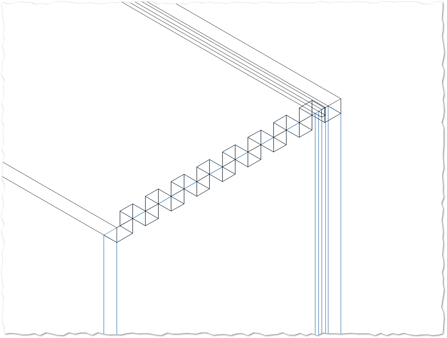
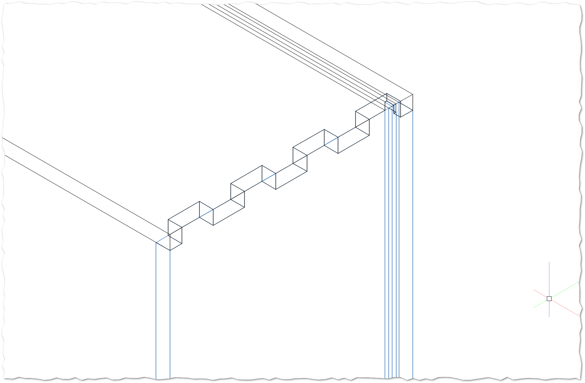
Example2: $BoxJointDiv = 10mm+1:n*45mm:45mm:n*45mm:10mm+1
The joints in example 2 are significantly wider, as 45mm>20mm.
Example: Box Joints between Middle Panel and Shelf
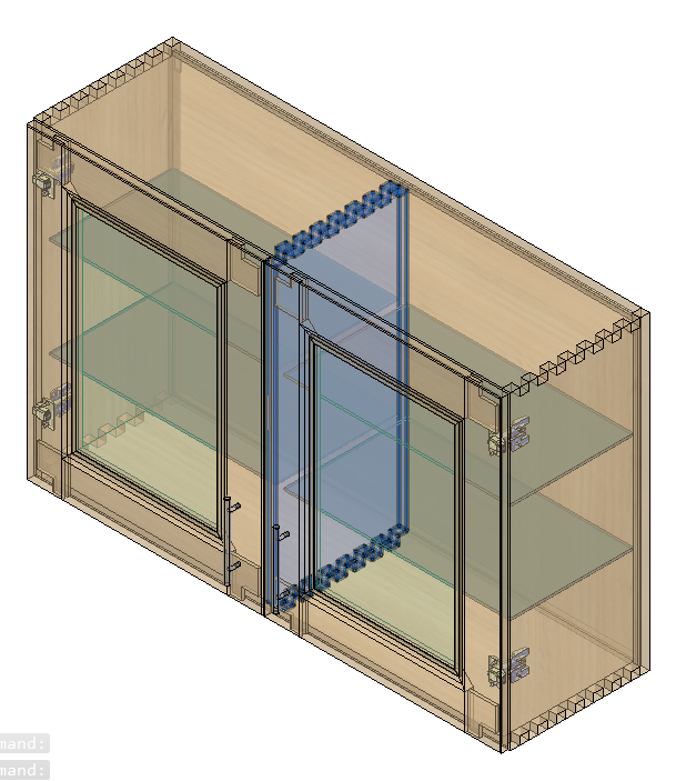
We want to use box joints to connect a middle panel with the top and bottom shelves.
Data Set-up in Detail
The article called "SW_MT_ProfileBoxJoin_MS" is a kitchen cabinet with a middle panel. The middle panel is to be connected to the top and bottom shelves using box joints.
In the following, we will take a closer look at the connection between the middle panel and the shelf in detail.
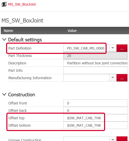
We use the Construction principle 'MS_SW_BoxJoint' for the middle panel. For the upper and lower edges, an offset is defined. The offset is defined using a variable so that it corresponds to the thickness of the top and bottom shelves.
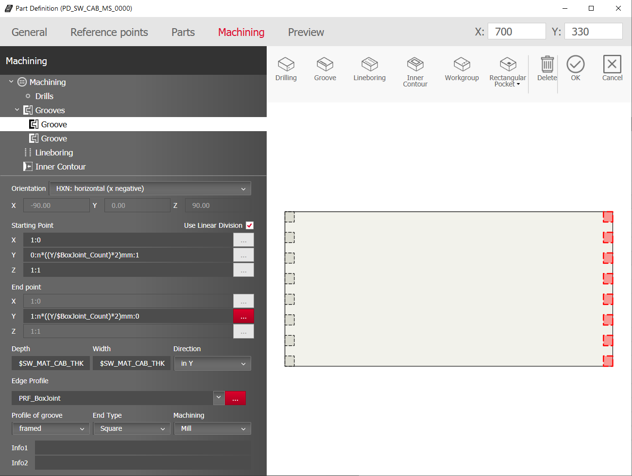
Groove 1:
| Start point: |
X= 1:0 Y= 0:n*((Y/$BoxJoint_Count)*2)mm:1 Z= 1:1 |
| End point: | Y= 1:n*((Y/$BoxJoint_Count)*2)mm:0 |
Groove 2:
| Start point: |
X= 0:1 Y= 0:n*((Y/$BoxJoint_Count)*2)mm:1 Z= 1:1 |
| End point: | Y= 1:n*((Y/$BoxJoint_Count)*2)mm:0 |
Depth and width of the grooves: The values for the depth and width of the groove take into account the material thicknesses of the middle panel, top shelf, and bottom shelf. Variables are useful for this. In the example, the material thicknesses of the parts are identical and defined via the variable $SW_MAT_CAB.
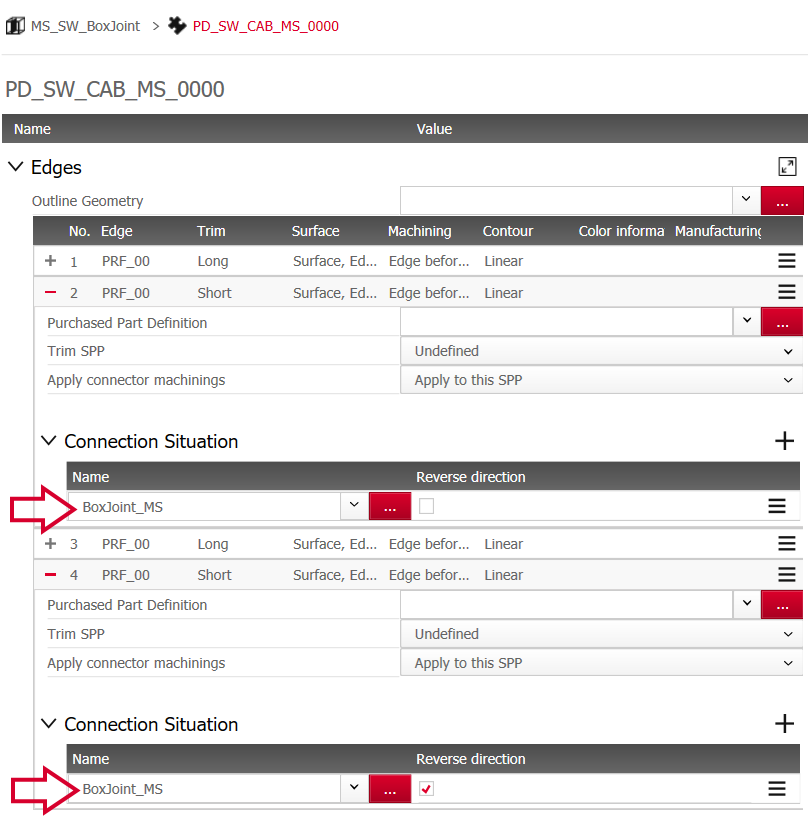
In the Part Definition of the middle panel, the Connection Situation "BoxJointA_0" is assigned to edges 2 and 4.
At edge 4, the checkbox "Reverse direction" is also checked in order to reuse the same Connection Situation by "mirroring".
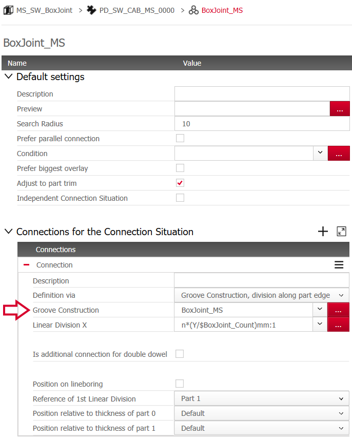
"BoxJoint_MS" consists of a Connection defined as follows:
- Definition via = Groove construction, division along part edge
- Groove construction = BoxJoint_MS
- Linear division X = n*(Y/$BoxJointCount)mm:1
In the Linear Division, a variable is used to quickly change the widths of the joints later via the variable dialog.
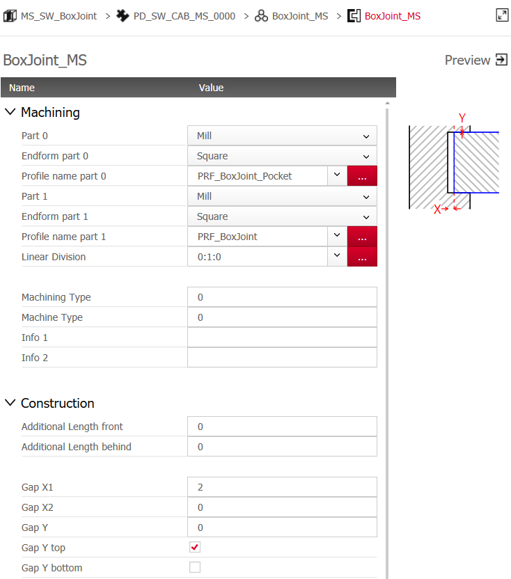
The groove construction "BoxJoint_MS" creates appropriate cutouts in the top and bottom shelves and has the following characteristics:
- Linear Division = 0:1:0
- Gap X1 = 2
The middle panel is now fully configured.