
Part Editor - Reference Points/ Auxiliary Points
Access
Element Manager > Construction Principle > Parts > Part Definition > Basic settings > Part category
General Information
Here you have the option of creating different types of Reference points – either by means of Linear division or by means of the Intersection of lines that are aligned parallel to the part edges. Depending on the type of Reference point you are editing, the Interactive Graphic and the availability of properties will change.
Create Reference points using Linear divisions
With the help of the linear division you can create a number of construction points for the MPE . You can use these points to define the starting point and end point of a SPP or you can use the construction points to define the edges of the daughter elements.
To generate a reference point, click on New Linear Division in the toolbar. Define a Linear division in X and Y in the Properties sidebar and click the button Apply (check-mark).
Reference points created from linear divisions are displayed in yellow in the preview.
See Options - Reference points via Linear division .
Reference points from intersections of part contours
With the help of the part contours intersections in the X and Y planes can be defined for Multi-part Elements . You can use these points to define the starting point and end point of a SPP or you can use the intersection points to define the edges of the daughter elements.
To generate an intersection point select an edge below the entry Intersection (line) 1 and Intersection (line) 2 . When the two edges intersect at the point you want, you can use the button Apply to generate the intersection point.
Reference points created from intersection points are displayed in green in the preview.
See Options - Reference points via part contours .
Variables and constants
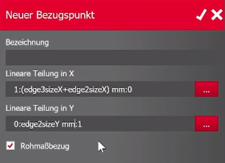
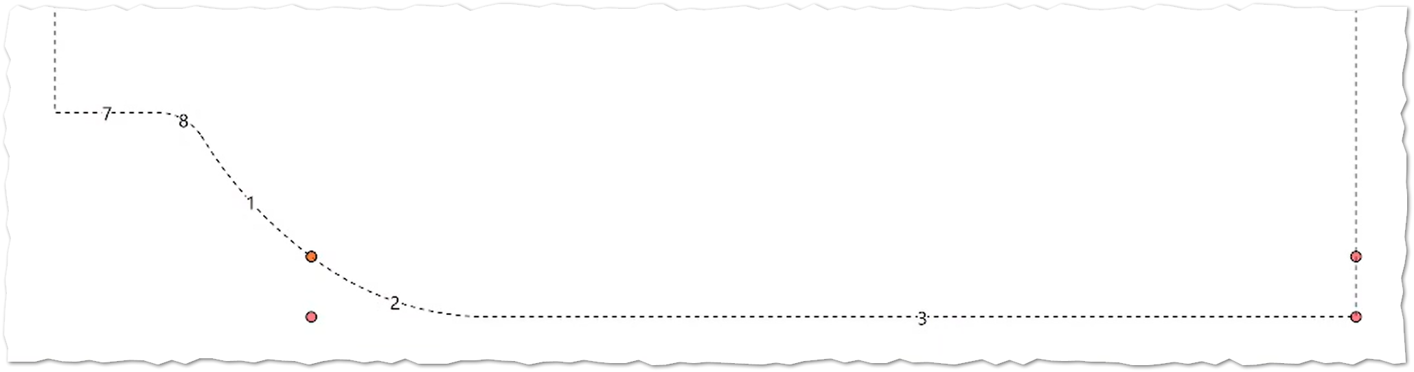
For the linear divisions in X and Y, you can use imos variables as well as the constants edge length in X and edge length in Y . The constants control the linear division depending on the current edge dimensions. This makes it possible, for example, to define doors with slanting edges (sloping roofs) without unintentionally skewing the points.
The constants are structured as follows:
edge<edge number>sizeX = edge dimension in the X direction. Example: edge1sizeX.
edge<edge number>sizeY = edge dimension in the Y direction. Example: edge1sizeY.
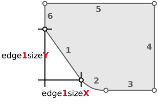
Example:
Tools
| New Linear Division |
Create new Reference points using Linear divisions. The interactive graphic and the availability of properties in the sidebar change according to the reference point type Linear Division . |
| New Intersection |
Create a new Reference point using the intersection of part contours. The interactive graphic and the availability of properties in the sidebar change according to the reference point type Intersection . |
| Delete | Delete points that you have selected in the tree Reference points . |
Options - Reference points via Linear division
The options are available when
- you click on the tool New Linear Division to create new reference points or
- you have selected Reference points in the tree to edit existing reference points.
| Apply (check-mark) |
Available when the options have been opened by clicking on the tool New Linear Division . With a click on the button, the definitions of the linear divisions are evaluated and the reference points are generated accordingly. The points appear in the tree above. |
| Discard/ Cancel |
Available when the options have been opened by clicking on the tool New Linear Division . Cancels the New Linear Division process and discards current entries in the options. |
| Name | Name the tree node under which the reference points should be grouped. |
| Linear Division X |
With the help of the linear division you can define the position and number of the reference points. Context menu:
See also Variables and constants . |
| Linear Division Y |
With the help of the linear division you can define the position and number of the construction points. Context menu:
See also Variables and constants . |
| Raw size reference |
The 'Raw Size Reference' option controls which type of part dimension is used when placing reference points. (see 'Part Dimensions - Types of Dimensional References') If the checkbox is ticked, the linear divisions and intersection points are applied to the raw dimension. If the checkbox is NOT ticked, the linear divisions and intersection points are applied to the final dimension. Example: Each edge of a multi-part has a 2mm thick ABS edge banding assigned
to it.
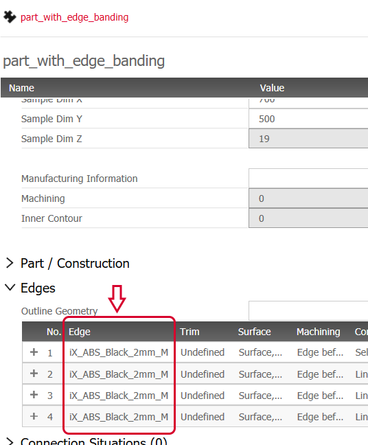 In the Part Editor, the following linear divisions are defined for the reference points:
Therefore, the reference points should theoretically be placed exactly at the corners of the parts. If the 'Raw Size Reference' checkbox is ticked, the reference points
will also appear at the part corners in the preview area.
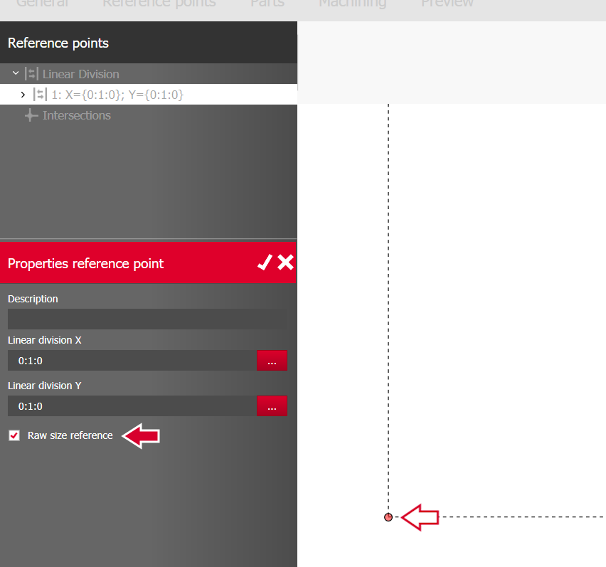 If the 'Raw Size Reference' checkbox is NOT ticked, the reference
points will NOT appear at the part corners in the preview area, but
rather 2mm away in both the X and Y directions. This is because the
preview shows the outline of the part including the 2mm thick edge
banding.
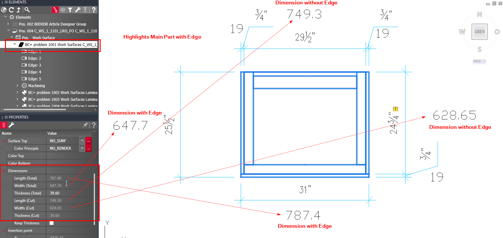
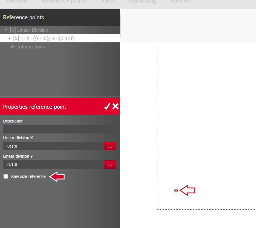 Recommendation: Do NOT tick the 'Raw Size Reference' checkbox when placing reference points for a multi-part or specifically a sandwich part. This allows you to always see the position of the child parts (defined using the reference points) in relation to the entire parent part. Note: When you select the part in the iX CAD drawing area, the
highlighting of the part will correspond to the raw
dimensions.
 |
Options - Reference points via part contours
The options are available when
- you click on the tool New Intersection to create new reference points or
- you have selected Reference points in the tree to edit existing reference points.
| Apply (check-mark) |
Available when the options have been opened by clicking on the tool New Intersection . The intersection point is calculated from the intersection of the contour lines 1 and 2. With a click on the button, the intersection is generated and listed in the tree above. |
| Discard/ Cancel |
Available when the options have been opened by clicking on the tool New Intersection . Cancels the New Intersection process and discards current entries in the options. |
| Intersection 1/ Intersection 2 | In the selection lists Intersection 1 and 2, all edges of the part contour are listed. Clicking on one of the edges selects it. |
| Distance to outside contour |
The function shifts the intersection line by the entered value in relation to the edge. Context menu:
|
| Extension at ends |
With this function, the intersection line is extended by the entered value in relation to the edge. Context menu:
|
| Raw size reference | If the function is activated the distance and therefore the intersection points will be generated related to the raw size of the multiple part. |