
Contiguous Parts
Thanks to the integration of the new iXplorer in PLAN iX 2019 there are now extensive options available to edit contiguous parts.
Integration Modifier
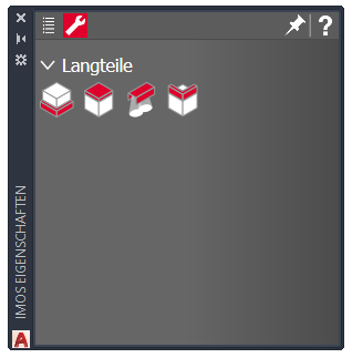
The imos Properties palette offers modifiers and methods to adapt articles in detail.
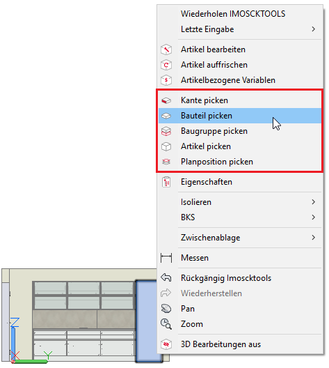
A distinction is made between part-specific and edge-specific modifiers and methods for contiguous parts. Their availability depends on the object selected. You select the different types of objects by opening the context menu with a right-click in the drawing area and then click one of the following options:
- Pick edge
- Select
- Select subassembly
- Pick article
- Select plan positions
Part-specific modifiers
| Modifier | Definition | |
|---|---|---|
|
Join
|
Join two parts with contiguous edges to become one | |
|
Transfer AutoCAD elements as inner contour
|
Continuous / fixed depth Continuous / fixed depth Profile principle |
|
|
Cutting principle - along edges
|
Linear Division Cutting principle Angle |
|
|
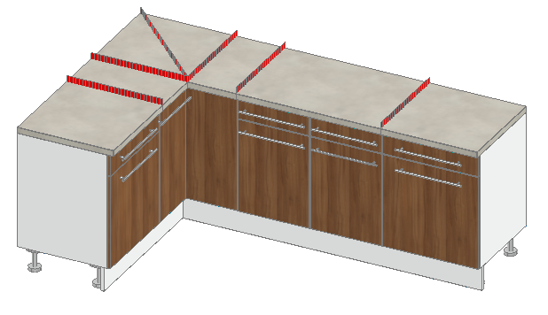
Cutting principle – with selection of cutting line
|
Cut work surface by selecting predefined cutting lines in the drawing area: 3x on corner, on each article butt joint, at wall offset |
|


Edge-specific methods
| Modifier | Definition | |
|---|---|---|
|
Apply Connector
|
Connector principle Linear Division Backset Offset |
|
|
Butt Joint
|
Select part to which a butt joint is to be created | |
|
Edge adjust
|
Select another edge, which should be adjusted | |
|
Extend to Polyline
|
Pick a polyline which the edge should adjust to Snap radius |
|
|
Move edge
|
Offset Value |
|
|
Split Part Along Edge
|
Linear Division Cutting principle Angle |
|


Article-specific methods
| Method | Definition | |
|---|---|---|
|
Base
|
Generate base under selected articles panel | |
|
Work surface
|
Generate work surface above selected articles | |
|
Light valance
|
Generate light valance under selected articles | |
|
Top valance
|
Generate crown molding above selected articles | |


Modifier Dialog
It is possible to make detailed adjustments to articles and individual parts in the Modifier dialog boxes. When you select a base, for example, the properties palette lists the modifiable properties of the contiguous part. When you have finished making changes, click the tick icon in the Elements palette to confirm them or click the cross icon to discard them.
Planning contiguous parts
Planning contiguous parts is described below using work surfaces as examples
In addition to automatically and retrospectively generating work surfaces via the Configurator, you can also use the method Work surface. This is displayed on the Methods tab on the iXplorer Properties palette as soon as you select one or several articles.
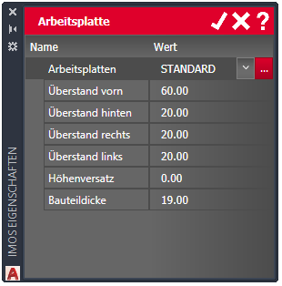
When you click the method, the Properties palette displays the Methods dialog box, in which you can alter the principle, over-sizes, height offset as well as the part thickness. When you have finished making changes, click the tick icon in the Elements palette to confirm them or click the cross icon to discard them.
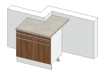
If a base unit is arranged against an offset wall with an offset of less than 300 mm, the work surface is automatically set back against the wall.
Using the cutting principle and the command With selection of cutting line, cut the work surface into appropriate sections along one of the suggested red cutting lines; Select the desired cutting principle in the Methods dialog box, then click the tick icon to confirm the settings. After they are cut, the created sections are subsequently listed as separate positions in the BOM.
May 2019 | imos iX 2019
#01137