
iX2019 PLAN - Inserting articles
Inserting and moving
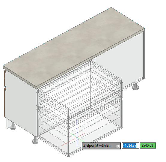
Beginning with the version iX 2019 articles are aligned depend-ing on where the mouse pointer is located and are inserted per left-click; the mouse pointer holds the article at its geometric center The bounding box sticks to the cursor with its geometric center. Left-click to insert the article.
In the Article category you define eight snap points for the bounding box of the article and, if necessary, specify the insertion height.
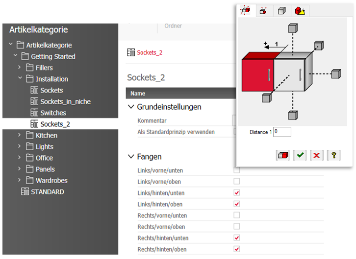
If there are no objects in the drawing area the article’s bottom side is aligned on the XY-plane of the WCS (at Z=0).
In addition, snap points will snap according to the target point, the distance between different snap points and the context.
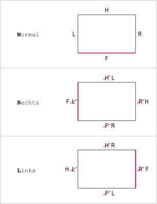
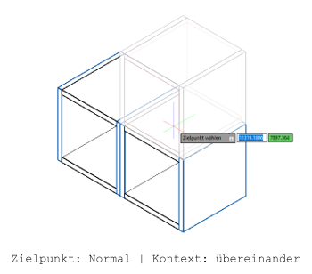
The target points Normal (default), Right and Left define how the bounding box’s sides are allocated. 'Normal' means that the bounding box’s front matches the article’s front.. If you select 'Right', the allocation turns 90° counter-clockwise so that the article’s front becomes the bounding box’s right side;. If you select Left, the allocation turns clockwise so that the article’s front becomes the bounding box’s left side.
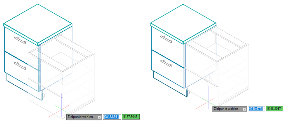
An intersect detection function prevents collisions with walls, floors, ceilings and other articles.
The snap points of the article to be inserted snap automatically as soon as it collides with another article side.
Which specific snap points are snapped depends on the context. Within a context, the points with the smallest distance to each other snap to each other.
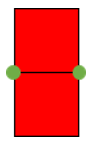
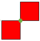
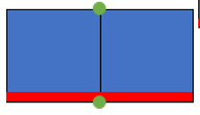
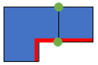
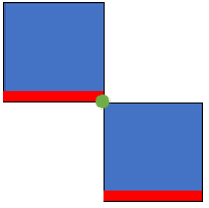
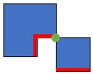
For example, with the default target value Normal, the following points will be snapped on base units that have the Article Category 'AC_K_BU_WS' (fronts are highlighted red):
| Context | Description | Pictogram | (example) |
|---|---|---|---|
| Next to each other |
rear-left – rear-right & front-left – front-right (outsides of corner cabinets) |
|
Kitchen counter |
|
front-right – rear-left/ rear-right – front-left (outsides of corner cabinets) |
|
||
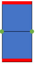
| Back to back | rear-left – rear-right & rear-right – rear-left |
|
Kitchen island |
|
rear-left – rear-left / rear-right – rear-right (outsides of corner cabinets) |
|
||
| On top of one an-other | top-left – bottom-left & top-right – bottom-right |
|
Stackable rack |
|
top-left – bottom-right/ top-right – bottom-left/ top-front – top-rear/ top-rear – top-front |
|
||
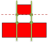
| snap points align vertically (insertion height corresponds to the dashed line) |
|
Kitchen wall cabinets | |
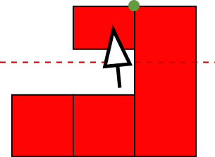
| snap points only overwrite the insertion height if they are higher than them; for example, when inserting a wall cabinet next to a tall cabinet |
|
||
| Without snap points | snap on the next horizontal surface on which the cur-sor is located |

|
decoration articles, lamps on the ceiling |
| Wall | article aligns automatically with back to wall |

|
|
| snap points automatically snap other article snap points within a radius of 60 mm |

|
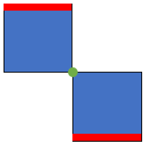
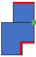
* Fronts are highlighted red
|
|
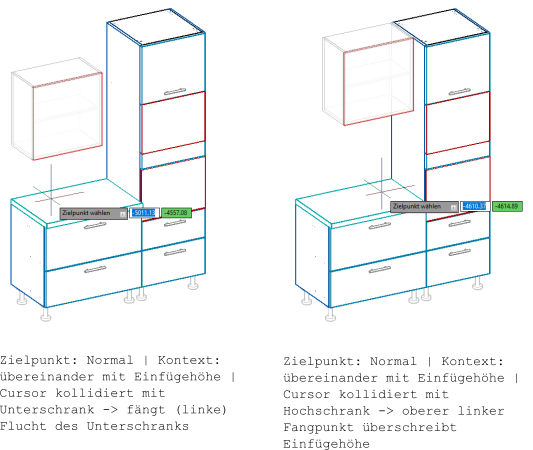
|
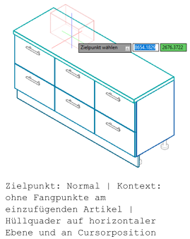
|

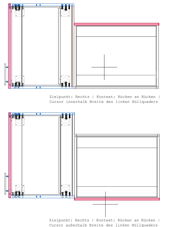
In addition, when choosing the target points Right or Left in the 'back to back' context, you may flip the article’s front to the other side by simply moving the mouse pointer beyond the other article’s width. This allows you to decide how to continue the cabinet line.
If the orientation of an article being moved differs from 0°/ 90°/ 180°/ 270°, it will be automatically rotated “straight” again according to one of the stated angles.
Copy article
Instead of the function "Copy article" in the drawing area context menu, that requires the article-mode to be active and that does not consider imos snap points, you can now simply use the more convenient function "Copy article" in the ribbon menu. In CAD it is located in the index tabs Article Designer and Main Data.
Highlighting article fronts
A red highlighting of the front helps you placing the article correctly.
- In a solid visual style the entire front is highlighted in red;
- otherwise only the front borders are highlighted.
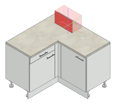
Note: For users who have a red–green color blindness, we recommend that you use the visual style '3dWireframe'.
Stretching articles and article lines
There are two ways of modifying article dimensions: when inserting or by using the methods Stretch article/ -article line.
First click the Stretch article method, then select an article.Right-click/ press ENTER to confirm your selection; Red grips appear on all article sides. An arrow indicates the stretch direction when you move the mouse pointer over the grips. Click the grip that points to your target stretch direction.
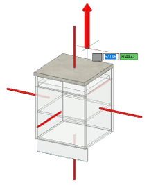
There are several options available to stretch the article:
By default it is possible to enter the coordinates of a point in the coordinate system in the pointer field or snap the points from AutoCAD. The difference between the start and end point on the axis is decisive for the final stretch operation.
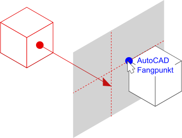
However, it is more practical to use the new functions for article handling or the options 'Overall size' and 'Difference' in the command line. For the latter, the cursor changes to 'dynamic input' to enter dimensions: For the Overall Size option, specify the actual width of the article or the article line; For the Difference option, specify only the dimension by which the article or selected elements of the article line should be stretched or squashed (negative value). Right-click / press ENTER to confirm your selection.

The change in dimension is not applied immediately to the article – you can check the result in the preview as well as repeat the stretch procedure by again clicking on a grip. Keep in mind that this does not undo your previous inputs for the increase/decrease in size.
Right-click/ press ENTER to terminate all stretch operations. When doing so, none of the stretch-arrows must be active.
To cancel the last command click ESC.
The difference between the methods Stretch article and Stretch article line is as follows:
Select one or several articles to be stretched; All articles arranged flush with one another form the article line. For example in a corner kitchen unit, the cabinets that follow on the corner cabinet's other side panel belong to the article line, too.
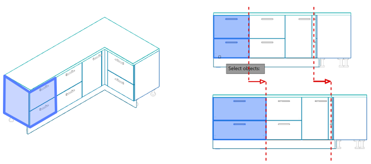
It is possible to add articles to the article line using the command 'Add objects' – conversely, it is possible to remove articles from the line using the command 'Remove objects'. Select target articles in the drawing area, then right-click/ press ENTER to confirm your selection.
Only selected articles in the line will be stretched by the specified increase in size. However, their proportions are retained, as is the case with the linear division of the article line.
Example
The widths of the rows of wall and base units of a kitchen differ, but are inserted next to the same tall cabinet. To make sure that both kitchen unit rows are flush, all three wall cabinets shall be stretched to the left.
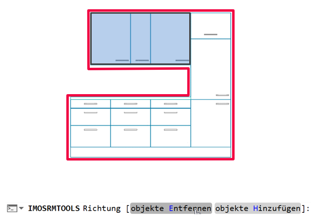
During the stretch operation, we interrupt the article line by removing the tall cabinet using the 'Remove objects' command; This also excludes the base cabinets from the article line.
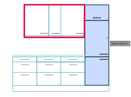
These would create gaps between the individual cabinets due to the alignments that do not match the wall cabinets when calculating the linear divisions. Gap-free stretching is guaranteed if they are excluded.
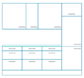
It is not possible to stretch all types of articles. This includes articles outside of the article line, corner cabinets, as well as articles with purchased articles, such as dish washers.
Reallocating position numbers
To assign new position numbers to selected elements, enter '#<number>' (e.g. #1) in the Pos. Number field of the Properties palette; Press ENTER to confirm your input.
The numbers, starting at 1 for “#1”, are allocated in the order the elements were selected.
May 2019| imos iX 2019
#01143