
Connection Situation
Access
imos Ribbon : Main data > Main data > Element Manager > Construction Principle > Connections > Connection Situation
Organizer > Tab Element Manager > Construction principles > Connections > Connection situations
General Information
A connector situation describes the combination of connections required to connect parts to each other.
Different connections can be defined on e.g. a part edge.For example, a dowel connection in combination with an cam connection is combined into a dowel-cam-connection situation.
Procedure
Add
Click on the grey plus next to Connections for the Connection Situation to add a connection to a selected connection situation.
A new node is directly created in the grid.
As an alternative the sandwich button can be used add a further connection with the function New element .
Delete
Click on the sandwich button to delete an assigned connection. Select Delete !
Copy & Paste
With copy an paste a complete row can be duplicated. Click on the sandwich button and select the function!
Options
Default settings
| Description | Free defined text field. |
| Preview |
With this field you can allocate a preview for the connection situation. The preview is only for the display within the Element Manager. The preview can be loaded from any directory and should have an approximate size of 150 x 200 pixels. |
| Search Radius | Defines the search radius for the entire connection situation which is the radius for finding the connections. |
| Prefer parallel connection | Ensures that parallel connections will be preferred. |
| Condition | A condition can be assigned to the connection situation. |
| Prefer biggest overlay | Apply Connection Situation to the part with the biggest overlay if there are overlays with multiple parts. |
| Adjust to part trim |
In a Connection Situation, you can turn off the dependency of the part0/ part1 assignment on the part trim or on the part thickness by unchecking "Adjust to part trim" . Be default, the box is always checked. The checkbox is only evaluated when the part0/ part1 assignment is undefined which is true for... ... two door parts or ... two back wall parts. |
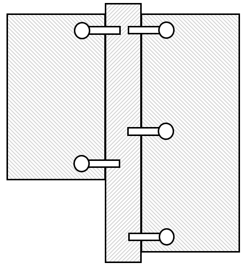
| Independent Connection Situation | Makes the Connection Situation independent, for example, to suppress the double-dowel logic (see image ). Note: As an alternative, you could use different Connection Situations for the left and right. |
Connections for the Connection Situation
Similar connector objects are combined in a connection. A connection describes the applied elements (connector objects) and the division of the objects (linear division).
Connections for the Connection Situation – Settings for Connection Type
| Description | Free defined text field. |
| Definition via |
You can select three four types: Connection type (Connection Scan) The definition of the connection with the connection types is the most frequently used allocation. If this definition is selected, you can select one of these types. After selecting the type, the possible connector sets are aligned. Direct selection You can directly choose a connector set for the connection situation. Groove construction If you select a groove generation, you can allocate a groove generation in the field below. These are administrated in the Element Manager as well. See also Groove generation. Only the properties for the positioning and the characteristics are activated with the groove generation. Tongue and groove joint If you select the tongue and groove joint, you can allocate a stretchable purchased part (SPP) as a connection. The linear division defines the length of the SPP. Furthermore, only the positioning and the characteristics are still activated. |
| Connection Types | Select a connection type from the Dropdown List. It contains all available types of connections. The selected connection type limits the number of the suggested connector sets. |
| Variant of machining | In each connector, several groups can be allocated . If necessary, restrict the selection in the Connection Situation by entering relevant group numbers separated by commas. |
| Selection |
This parameter is only activated if the option Connection type has been selected in the field Definition with . No connection type will be assigned to connection situation for the Direct selection, but a specific connector. Via a click on the button you will switch to the level of the connector,where you can choose a principle and assign it to the connection. |
| First linear division |
The linear division is a mathematical formula for the user to set it up individually which is suitable for every requirement by dividing any long line in different sections. The linear division is output as a string. Via a click on the button you change into Linear Division dialog. There you can define the division or load a descriptor file. |
| Second Linear Division | The second Linear division is only relevant if it is a surface connection. |
| Align on edge | Select the entry Yes from the dropdown box to automatically align the connector on the edge. |
| Rotation angle | With the entry of the rotation angle you can rotate the connector around the Z axis. |
| Snap radius | The snap radius defines the maximum distance in which imos searches possible existing partner parts to position the connectors. |
|
Is additional connection for Double dowel |
If two different shelves touch each other with the C-Constructions, then this setting can achieve that double dowels can be inserted and otherwise simple dowels in the overlapping area. |
| Positioning on lineboring | The function sets the machining of the connectors to the lineboring drillings. |
| Reference part of the First Linear Division |
Depending on if a second linear division has been activated or not, different parameters can be selected here. Parameters for one linear division (edge connection) Depending on the reference, another default value for the linear division can be the result. Select one of the four options from the Dropdown List. Minimum The linear division depends on the overlapping of part 0 and part 1. Maximum The linear division depends an the full length of part 0 plus part 1. Part 0 The linear division depends on the length of part 0. Part 0 always is the guiding part (onset). Part 1 The linear division depends on the length of part 1. Part 0 always is the guiding part (inset). Parameter for activated second linear division (area connection).Define the reference point of the connector. This point can have an effect on the linear division and the position of the connector. You can choose from the following entries for X- and Y-direction: Centric The insertion point is in the middle of the connector (centre of the pull) The insertion point "Centered" matches the characteristic-value "Handle_Insert" in positive X-direction. First insert point The first insertion point is identical to the actual insertion point of the connector. Second insertion point The second insertion point is always two times the characteristic-value "Handle_Insert" in positive X-direction. |
| Position relative to Part Thickness |
Define the position of the connection related to the part thickness.
If no second Linear Division has been defined, you can define the reference point of part 0 and part 1 independently. Parameters for one linear division (edge connection)Define the position of the connection related to the part thickness. You can define the reference point of part 0 and part 1 independently. Parameter for activated second linear division (area connection).Define the position of the connection related to part 0. For the option Default in most cases the option inside is used, because imos inserts the connection automatically as it applies in most cases. The geometrical differentiation between inside and outside depends on how the connected parts correlates to each other. |

Connections for the Connection Situation – Settings for Direct selection
| Description | Free defined text field. |
| Definition via |
You can select three four types: Connection type (Connection Scan) The definition of the connection with the connection types is the most frequently used allocation. If this definition is selected, you can select one of these types. After selecting the type, the possible connector sets are aligned. Direct selection You can directly choose a connector set for the connection situation. Groove construction If you select a groove generation, you can allocate a groove generation in the field below. These are administrated in the Element Manager as well. See also Groove generation. Only the properties for the positioning and the characteristics are activated with the groove generation. Tongue and groove joint If you select the tongue and groove joint, you can allocate a stretchable purchased part (SPP) as a connection. The linear division defines the length of the SPP. Furthermore, only the positioning and the characteristics are still activated. |
| Variant of machining |
The field is used to set up a connector with different machinings. The field is located in the Connection Situations and in the machining configuration for Connectors. Example: For some connectors, two drilling patterns are needed as variants, such as when they are used in both 32mm and 25mm drilling grids, and thus need different patterns. Instead of creating 2 connectors with the corresponding workgroup, you can use the “Variant of machining” field. In the machining settings of the Connector, an integer number has to be entered in the corresponding field. In the Connection Situation, one or many integer numbers (separated by comma) can be used as well as numeric variables. The entered value determines which machining variant of the connector will be evaluated. If no value is entered in the connection, all variants will be evaluated. |
| Selection | No connection type will be assigned to connection situation for the Direct selection, but a specific connector. Via a click on the button you will switch to the level of the connector,where you can choose a principle and assign it to the connection. |
| First linear division |
The linear division is a mathematical formula for the user to set it up individually which is suitable for every requirement by dividing any long line in different sections. The linear division is output as a string. Via a click on the button you change into Linear Division dialog. There you can define the division or load a descriptor file. |
| Second Linear Division | The second Linear division is only relevant if it is a surface connection. |
| Align on edge | Select the entry Yes from the dropdown box to automatically align the connector on the edge. |
| Rotation angle | With the entry of the rotation angle you can rotate the connector around the Z axis. |
| Snap radius | The snap radius defines the maximum distance in which imos searches possible existing partner parts to position the connectors. |
|
Is additional connection for Double dowel |
If two different shelves touch each other with the C-Constructions, then this setting can achieve that double dowels can be inserted and otherwise simple dowels in the overlapping area. |
| Positioning on lineboring | The function sets the machining of the connectors to the lineboring drillings. |
| Reference part of the First Linear Division |
Depending on if a second linear division has been activated or not, different parameters can be selected here. Parameters for one linear division (edge connection) Depending on the reference, another default value for the linear division can be the result. Select one of the four options from the Dropdown List. Minimum The linear division depends on the overlapping of part 0 and part 1. Maximum The linear division depends an the full length of part 0 plus part 1. Part 0 The linear division depends on the length of part 0. Part 0 always is the guiding part (onset). Part 1 The linear division depends on the length of part 1. Part 0 always is the guiding part (inset). Parameter for activated second linear division (area connection).Define the reference point of the connector. This point can have an effect on the linear division and the position of the connector. You can choose from the following entries for X- and Y-direction: Centric The insertion point is in the middle of the connector (centre of the pull) The insertion point "Centered" matches the characteristic-value "Handle_Insert" in positive X-direction. First insert point The first insertion point is identical to the actual insertion point of the connector. Second insertion point The second insertion point is always two times the characteristic-value "Handle_Insert" in positive X-direction. |
| Position relative to Part Thickness |
Define the position of the connection related to the part thickness.
If no second Linear Division has been defined, you can define the reference point of part 0 and part 1 independently. Parameters for one linear division (edge connection)Define the position of the connection related to the part thickness. You can define the reference point of part 0 and part 1 independently. Parameter for activated second linear division (area connection).Define the position of the connection related to part 0. For the option Default in most cases the option inside is used, because imos inserts the connection automatically as it applies in most cases. The geometrical differentiation between inside and outside depends on how the connected parts correlates to each other. |
Connections for the Connection Situation – Setting for the Groove Construction
| Description | Free defined text field. |
| Definition via |
You can select three four types: Connection type (Connection Scan) The definition of the connection with the connection types is the most frequently used allocation. If this definition is selected, you can select one of these types. After selecting the type, the possible connector sets are aligned. Direct selection You can directly choose a connector set for the connection situation. Groove construction If you select a groove generation, you can allocate a groove generation in the field below. These are administrated in the Element Manager as well. See also Groove generation. Only the properties for the positioning and the characteristics are activated with the groove generation. Tongue and groove joint If you select the tongue and groove joint, you can allocate a stretchable purchased part (SPP) as a connection. The linear division defines the length of the SPP. Furthermore, only the positioning and the characteristics are still activated. |
| Groove construction |
This parameter is only activated if the option Groove Construction or Direct selection has been selected in the field Definition with . Via a click on the button you will switch to the level of the groove constructions,where you can choose a principle and assign it to the connection. The Dropdown Box contains the last used groove constructions. |
|
Is additional connection for Double dowel |
If two different shelves touch each other with the C-Constructions, then this setting can achieve that double dowels can be inserted and otherwise simple dowels in the overlapping area. |
| Positioning on lineboring | The function sets the machining of the connectors to the lineboring drillings. |
| Reference part of the First Linear Division |
Depending on if a second linear division has been activated or not, different parameters can be selected here. Parameters for one linear division (edge connection) Depending on the reference, another default value for the linear division can be the result. Select one of the four options from the Dropdown List. Minimum The linear division depends on the overlapping of part 0 and part 1. Maximum The linear division depends an the full length of part 0 plus part 1. Part 0 The linear division depends on the length of part 0. Part 0 always is the guiding part (onset). Part 1 The linear division depends on the length of part 1. Part 0 always is the guiding part (inset). Parameter for activated second linear division (area connection).Define the reference point of the connector. This point can have an effect on the linear division and the position of the connector. You can choose from the following entries for X- and Y-direction: Centric The insertion point is in the middle of the connector (centre of the pull) The insertion point "Centered" matches the characteristic-value "Handle_Insert" in positive X-direction. First insert point The first insertion point is identical to the actual insertion point of the connector. Second insertion point The second insertion point is always two times the characteristic-value "Handle_Insert" in positive X-direction. |
| Position relative to Part Thickness |
Define the position of the connection related to the part thickness.
If no second Linear Division has been defined, you can define the reference point of part 0 and part 1 independently. Parameters for one linear division (edge connection)Define the position of the connection related to the part thickness. You can define the reference point of part 0 and part 1 independently. Parameter for activated second linear division (area connection).Define the position of the connection related to part 0. For the option Default in most cases the option inside is used, because imos inserts the connection automatically as it applies in most cases. The geometrical differentiation between inside and outside depends on how the connected parts correlates to each other. |
Connections for the Connection Situation – Settings for Tongue and groove joint
| Description | Free defined text field. |
| Definition via |
You can select three four types: Connection type (Connection Scan) The definition of the connection with the connection types is the most frequently used allocation. If this definition is selected, you can select one of these types. After selecting the type, the possible connector sets are aligned. Direct selection You can directly choose a connector set for the connection situation. Groove construction If you select a groove generation, you can allocate a groove generation in the field below. These are administrated in the Element Manager as well. See also Groove generation. Only the properties for the positioning and the characteristics are activated with the groove generation. Tongue and groove joint If you select the tongue and groove joint, you can allocate a stretchable purchased part (SPP) as a connection. The linear division defines the length of the SPP. Furthermore, only the positioning and the characteristics are still activated. |
| Tongue and groove joint |
This parameter is only activated if the option Tongue and groove joint has been selected in the field Definition with . Via a click on the button you will switch to the level of the SPP,where you can choose a principle and assign it to the connection. The Dropdown Box contains the last used groove constructions. |
| Linear Division X |
This parameter is only activated if the option Tongue and groove joint has been selected in the field Definition with . You can define the length and discontinuity for the tongue and groove joint with the linear division. |
|
Is additional connection for Double dowel |
If two different shelves touch each other with the C-Constructions, then this setting can achieve that double dowels can be inserted and otherwise simple dowels in the overlapping area. |
| Positioning on lineboring | The function sets the machining of the connectors to the lineboring drillings. |
| Reference part of the First Linear Division |
Depending on if a second linear division has been activated or not, different parameters can be selected here. Parameters for one linear division (edge connection) Depending on the reference, another default value for the linear division can be the result. Select one of the four options from the Dropdown List. Minimum The linear division depends on the overlapping of part 0 and part 1. Maximum The linear division depends an the full length of part 0 plus part 1. Part 0 The linear division depends on the length of part 0. Part 0 always is the guiding part (onset). Part 1 The linear division depends on the length of part 1. Part 0 always is the guiding part (inset). Parameter for activated second linear division (area connection).Define the reference point of the connector. This point can have an effect on the linear division and the position of the connector. You can choose from the following entries for X- and Y-direction: Centric The insertion point is in the middle of the connector (centre of the pull) The insertion point "Centered" matches the characteristic-value "Handle_Insert" in positive X-direction. First insert point The first insertion point is identical to the actual insertion point of the connector. Second insertion point The second insertion point is always two times the characteristic-value "Handle_Insert" in positive X-direction. |
| Position relative to Part Thickness |
Define the position of the connection related to the part thickness.
If no second Linear Division has been defined, you can define the reference point of part 0 and part 1 independently. Parameters for one linear division (edge connection)Define the position of the connection related to the part thickness. You can define the reference point of part 0 and part 1 independently. Parameter for activated second linear division (area connection).Define the position of the connection related to part 0. For the option Default in most cases the option inside is used, because imos inserts the connection automatically as it applies in most cases. The geometrical differentiation between inside and outside depends on how the connected parts correlates to each other. |
Characteristic
By generating the article, the construction is analyzed concerning the listed characteristics.
The results of this analysis have an effect on the suggested connector sets.
For example, if the depth of the carcases is 450 mm, then e.g. the drawer elements, which are suitable for this insertion situation, are only provided.
If you enter a fixed characteristic value for one of the characteristics, then this characteristic is not included in the analysis. This means that if another value results from the article construction, then this value is overmodulated from the entered characteristic value.
The listed characteristics are a result of the assigned conne ction types.
Related topics: