
Measure in the 3D preview
You can now use part-related measurement points to determine the length and position of geometry elements. There is a separate tab for this in the left sidebar.
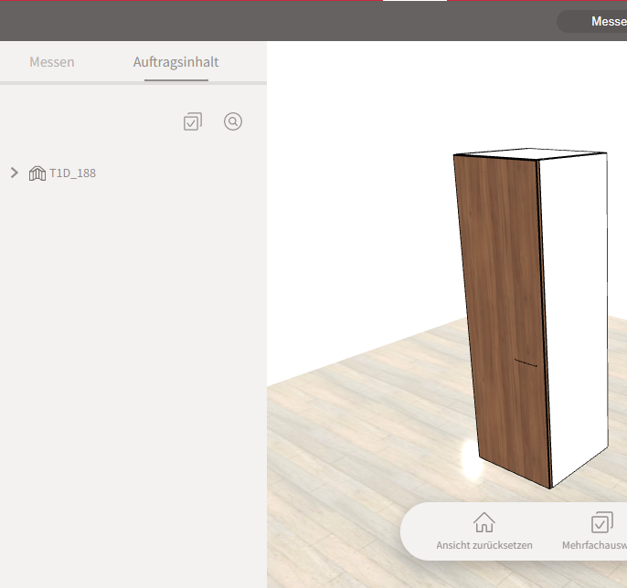
If you select a part and switch to this tab, or you select a part in the tab, the system isolates the part and displays available measurement points.
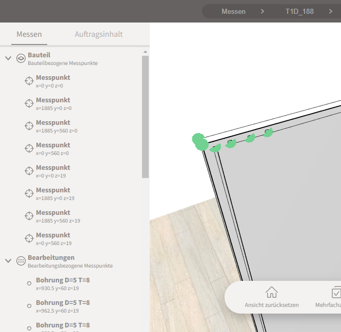
Valid geometry objects with their available measurement points are listed below:
- Outer contour: corner points
- Bore hole: center point
- Line boring: center point of the first and last hole in the grid
- Groove: start and end point
- Rabbet: start and end point
- Circular pocket: center point
- Rectangular pocket: middle point of each side of the rectangle
You can select the points in the 3D preview or in the tree in the sidebar.
In the tree, each measurement point of a machining also shows basic info such as the diameter and depth of a bore hole or the width of a groove.
If you select two points, they are put in relation to each other and the result is displayed in the lower area of the sidebar. Here the result is output as a direct distance as well as the distance in X, Y and Z.
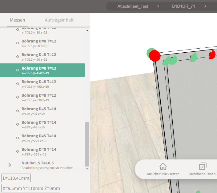
If you select a third point, it will be placed in relation to the last selected point. The first point is automatically removed from the selection.