
Insert an article in the drawing area
Access
iXplorer Article Center > Double-click on an article
Ribbon > Tab Designer > Method Move Article or Copy Article
General Information
The insert process for an article can be started
- by making a double-click on an article in the Article Center or by clicking the button with the spanner icon next to the article name
- by applying the method "Copy Article" on an existing article in the drawing area or
- by applying the method "Move Article" on an existing article.
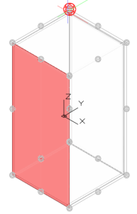
Beginning with the version iX 2019, articles are aligned depending on where the mouse pointer is located; the mouse pointer holds the article at its geometric center. Per left-click the article is inserted. A red highlighting of the front helps you placing the article correctly.
- In a solid visual style the entire front is highlighted in red;
- otherwise only the front borders are highlighted.
Note: We recommend users with a red–green color blindness to switch the visual style to 3dWireframe.
Furthermore, advanced options for positioning are available in the context menu and the command line during the insert process.
You can find information on other article related methods in Group Article .
Insert Options - Context menu
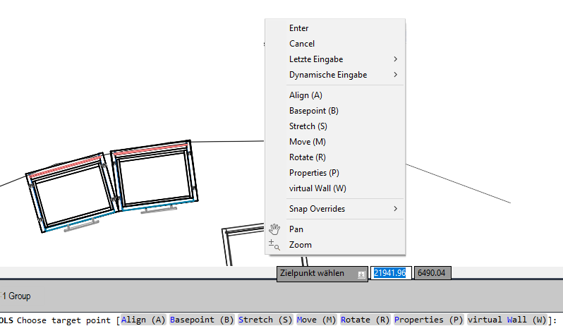
You can call up the context menu by right-clicking when the article is hanging on the mouse for positioning (insert mode). Left-click to insert the article and exit the insert mode.
The following are the methods available when inserting, moving, or copying an article from the context menu and command line. A special case are installation articles - See Define wall distances of installation objects when inserting .
Align
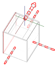
By left-clicking on one of the axes on the article, you determine its orientation.
Basepoint
An article can snap with its base point to snap points that the user selects.
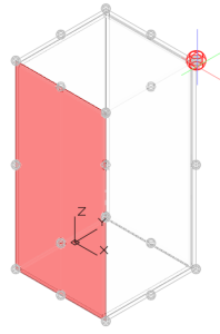
A standard article has 21 base points. They are located at the corners, edge centers and the center of the article. By default, the article center is selected as the base point. You can select a different base point from the context menu during insert mode.
When inserting by base point, snapping to article and wall snap points is temporarily switched off, so that you can select the target point to which the base point should snap.
Tip: To snap certain types of points during insert mode, press CTRL+Right-click . A context menu opens, in which you can select a point type to catch.
For easy identification, the selected base point is highlighted in color as long as the insert mode is active.
Notes:
- The following definitions from the Article principle still apply to the
article:
- Minimum insertion height
- Activated snap points of the Article Category
-
It makes no difference whether the previously inserted article
-
has no Article Category assigned
or
- has an Article Category assigned in which all article snap points are activated.
However, if it is assigned an Article Category in which only some of the snap points are activated, these snap points are decisive for snapping articles that are inserted next to it.
-
- In insert mode, the mouse pointer always moves over surfaces (walls, floor, Z-plane at height 0). In the example above, after selecting the base point, the mouse pointer is at height 0 on the Z-plane and is displayed to the user there. The position of the mouse pointer has nothing to do with the selected base point. For example, if you move the article in a wall corner with a floor and walls, you can see very well how the mouse pointer changes from the floor surface to a wall surface and vice versa.
Position an article using a snap point and the base point:
To position an article using the selected base point, you must also select a point on which the base point is to be placed on.
Since the 2D object snap is turned off for the duration of positioning, you can instead use the keyboard shortcut SHIFT + right mouse button to specify a snap point type to be caught temporarily. On these points, the article can be placed with its selected base point.
Note: When setting the insertion point, imos automatically corrects the position of the article if the article would get an insertion height <0mm or penetrate a wall.
Examples
Example - Snap to a target point you defined
In insert mode, define the base point of the small cube.


Press CTRL+Right-click and select the point type Center.

The small cube snaps at the geometric centers of the large cube.

Base point selected at the top right, insertion point = 0,0,0
 -->
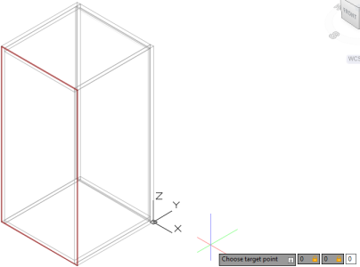 -->
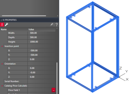
The position of the article is corrected "upwards" by imos until the article has an insertion height of at least Z=0mm. At the same time, you can see that the base point "right back" was used.
Base point selected at the top left, insertion point = 0,0,0
 -->
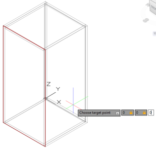 -->
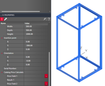
In this example the position of the article is corrected "upwards" by imos as well until the article has an insertion height of at least Z=0mm. At the same time, you can see that the base point "left back" was used.
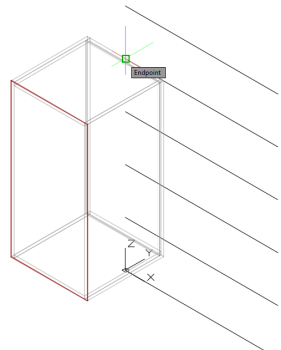
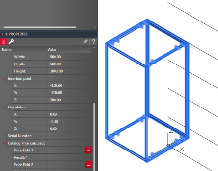
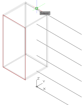
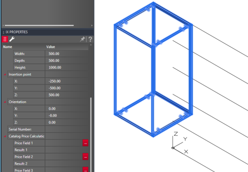
Example: Base point top back center, insertion point at different heights
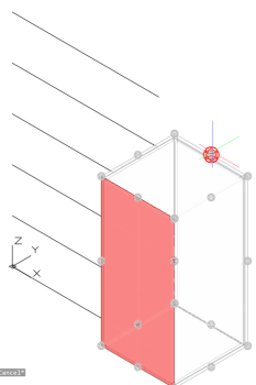
The elevation lines shown are Z=300, 600, 900, 1200, 1500mm.
The article height is 1000mm.
The left end of an elevation line is selected as the insertion point each (using SHIFT+right mouse button > End point).
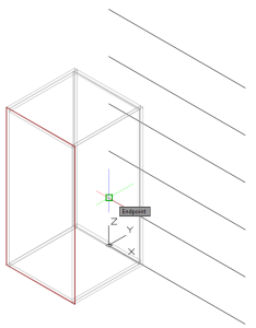
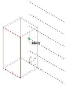
Result at insertion heights 300, 600 and 900mm:
In all these cases, imos avoids that the article is positioned with its lower edge below Z=0.
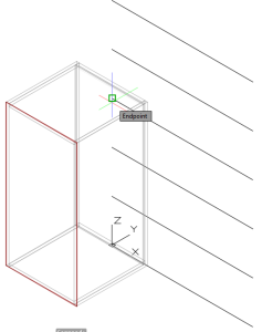
Result at insertion height 1200 and 1500mm:
In this case, the selected base point can be positioned at Z=1200mm/ 1500mm. The distance to Z=0 is 200mm/ 500mm.
Stretch
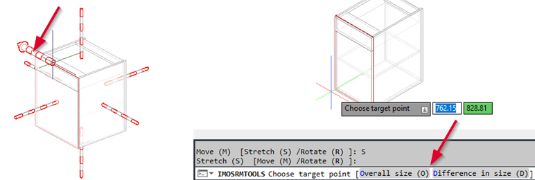
Left-click to select one of the axes along which the article should be stretched. In the command line or by invoking the context menu again, select the type of size change:
- a new Overall size, or
- a Difference in size that is to be added to or subtracted from the current total size.
Enter a value in the dynamic input and confirm with ENTER or right-click.
Note: The ability to change article dimensions is limited if the "Not stretchable" option is active in the Article Category assigned to the article:
- In iX PLAN
- You can only select from a list of predefined dimensions in the Configuration (Modify article).
- When inserting the article: In the Insert Properties dialog, the fields for the size change are not available.
- If the article is selected: In the iXplorer Properties palette, the fields for size change are deactivated.
- The "Stretch article" method is not applicable to the article.
- In iX CAD
- You can only change the article dimensions in the iXplorer Properties palette.
- When inserting the article: In the Insert Properties dialog, the fields for the size change are not available.
- The "Stretch article" method is not applicable to the article.
Move method
The "Move article" method can be found in the following spots in the program.
- Ribbon menu > Designer tab
- In the context menu of the drawing area, if the insert article mode is active
- In the context menu of the drawing area, if the insert article mode is inactive
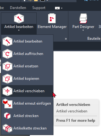
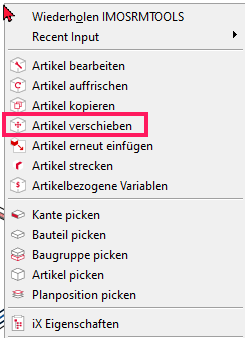
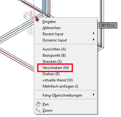
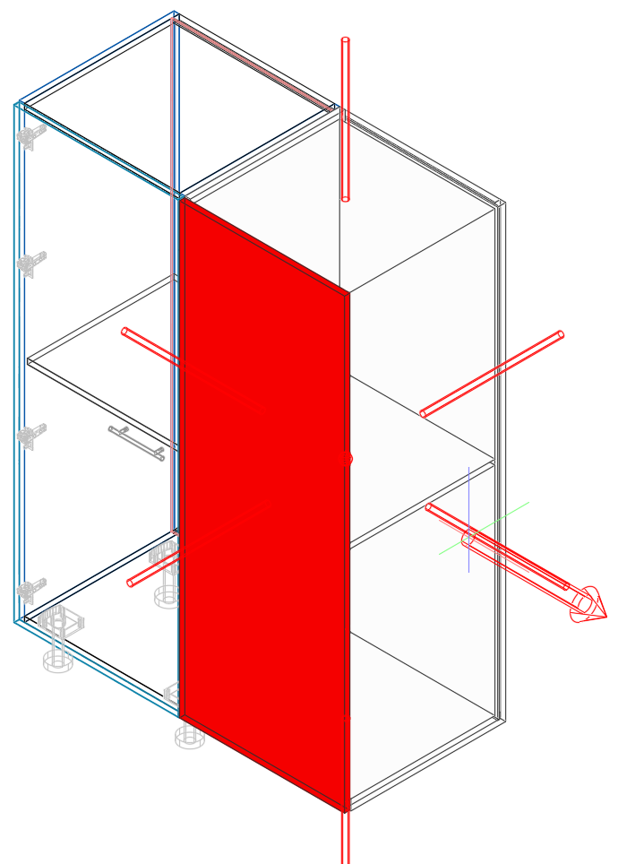
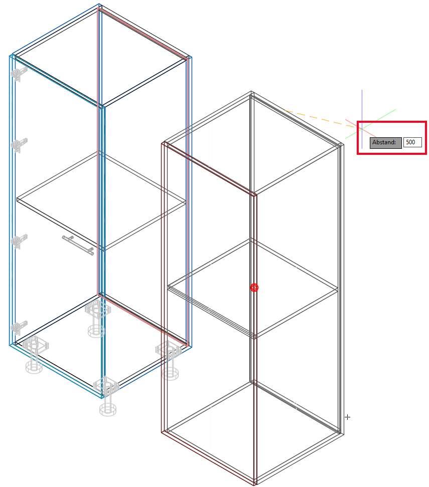
When you call the imos method "Move article", select an article and choose the direction (arrow) to move it, you can type in your desired offset dimension directly in the dynamic input and confirm it by pressing ENTER.
Rotate
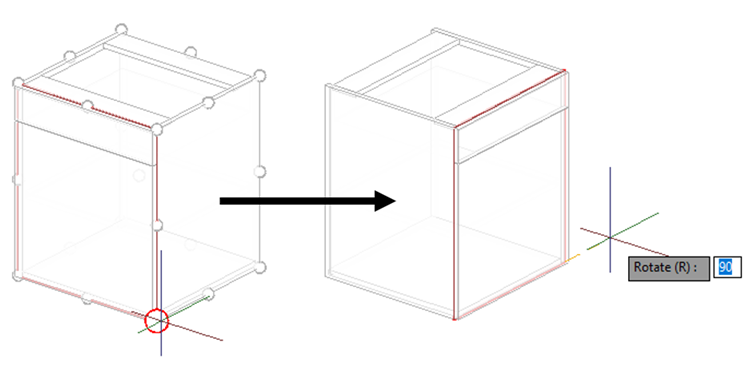
Select a node on the article around which you want to rotate the article. By default, the article is rotated around its Z-axis. In the command line or by invoking the context menu, you can also select the X or Y axis of the article as the axis of rotation. Enter a rotation angle in the Dynamic Input window and confirm the entry with ENTER or right-click. A positive value turns left, a negative value turns right.
Virtual Wall
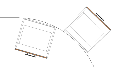
Select one or more lines, polylines, arcs or circles that you want to use as a virtual wall and confirm the selection with ENTER or right-click. Articles can be aligned on virtual walls as well as on the standard iX walls. The program remembers the selected virtual walls. In this way, further articles can be positioned on the virtual walls once selected. The link is canceled when you run the method again in the order.
Multiple Insert
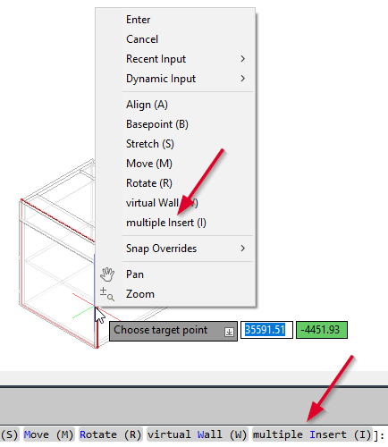
After clicking on "Multiple insert", the article currently on the mouse is inserted at its position. Then, imos calls a copy of the article you just inserted, which you can insert without further interaction.
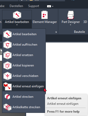
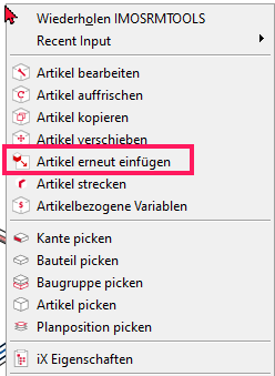
Reinsert article
The "Reinsert article" method activates the insert article mode for selected articles. Use the function if you want to position articles somewhere else later on.
- Click „Reinsert article“. You can find the function in the ribbon and in the
context menu of the drawing area.
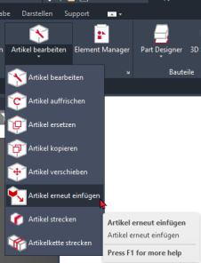
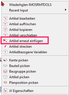
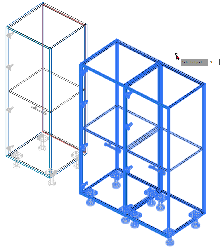
- Select one or more articles that you want to reposition. Right-click to
apply the selection.
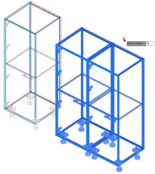
Result: The articles are sticking to the mouse pointer and the insert article mode is active, i.e. you can use the different snapping options and the functions of the context menu to position the article as you like.
Define wall distances of installation objects when inserting
When inserting installation objects, you can define distances along a wall the object snaps to. This allows the object to be positioned precisely on the wall.
Remember: An article is considered an installation object if the following is set in its Article principle: Installation object =Yes .

Procedure:
Prerequisite: You are in the process of inserting an installation object, i.e. the insert article mode is active.
- Move the mouse pointer, that the installation object is sticking to, over the desired wall so that it snaps to it.
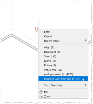
- Right-click to open the context menu and select the Distance
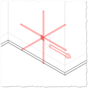
Wall (D) method. Directional arrows appear on the object.
- Click the arrow pointing in the direction where you want to define
the distance. The dynamic input pops up.
-
Enter the distance in the dynamic input . Confirm with the ENTER key. The direction arrows are displayed again.
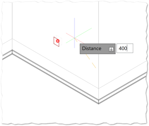
Info: The input is the distance at right angles between the central base point of the object and the nearest wall corner located in the selected direction.
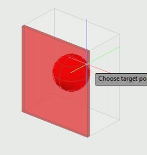
-
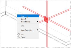
Optional: Define additional distances as described above.
-
Left-click in the free drawing area or press ENTER to insert the object. This takes all defined distances into account.
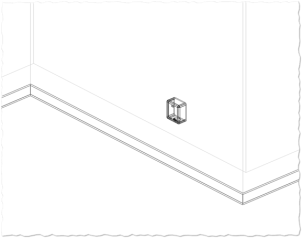


Availability of methods in the context menu
If positioning takes place in several steps (e.g. first move, then rotate, then move again), it is possible to call another insert method in the context menu after each of these steps without having to end the process.
Properties – Insert Article
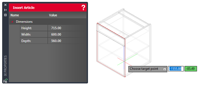
The article insert properties are loaded during the insert process in the iXplorer Properties palette. These allow
- a quick entry of all article dimensions and
- a quick change of article variables if a Variable List is assigned in the Article principle.
Note: The call of the properties is not offered in the context menu if "Not stretchable" is active in the assigned Article Category.
Note: A change of variables of a Variable List assigned to the article is not offered in iX Plan.
Exception Object Designer and FXF articles
FXF links and Object Designer articles are represented as cuboids in the insertion process, meaning only the corners of the cuboid can be snapped. In addition, the "Stretch article" method is not applicable to them.
English keyboard shortcuts are used independent of the user language.
Insert Options in the iXplorer Properties Palette
When inserting, moving or copying an article you can apply different settings to it. Namely:
- change article dimensions
- change variable values (available if a variables list is assigned to the article)
| Width | Define the width of your article in mm. |
| Height | Define the height of your article in mm. |
| Depth | Define the depth of your article in mm. |
| Insert with stretches | Activate the checkbox to stretch the article immediately after insertion. |
| Variables from a Variable List | Available, when a Variables List is assigned in the Article principle . You can change the values of the variables that are part of the list in the palette. |
Snap points
In the Article Category that is assigned to the article you can define 8 snap points. You can also determine an insertion height, if required.
If there are no imos objects in the drawing area the article’s bottom side is aligned on the XY-plane of the WCS (at Z=0). In addition, snap points will snap according to the target point , the distance between different snap points and the context .
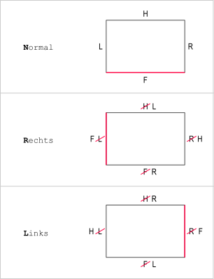
The target points Normal (default), Right and Left define how the bounding box’s sides are allocated. Normal means that the bounding box’s front matches the article’s front. If you select Right the allocation turns clockwise so that the article’s front becomes the bounding box’s right side. Vice versa, when selecting Left, the allocation turns counter-clockwise and the article’s front becomes the bounding box’s left side.
An intersect detection function prevents collisions with walls, floors, ceilings and other articles.
The snap points of the article to be inserted snap automatically as soon as it collides with another article's side. Which specific snap points are snapped depends on the context; the points snap that have the smallest distance between them.
In addition, when choosing the target points Right or Left in the context back to back, you may flip the article’s front to the other side by simply moving the mouse pointer beyond the other article’s width. This is useful when you wish to continue the article line either way on a cabinet’s back.
If the orientation of an article being moved differs from 0°/ 90°/ 180°/ 270°, it will be automatically rotated “straight” again according to one of the stated angles.
Examples for snap points
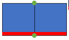
For example, with the default target value Normal , the following
points will be snapped on base units with the article category AC_K_BU_WS (fronts
are highlighted red):
| Context | Snap points | |
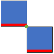
| Next to each other |
rear-left – rear-right & front-left – front-right (outsides of corner cabinets) |
|
|
front-right – rear-left rear-right – front-left (outsides of corner cabinets) |
|
|
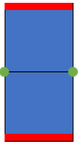
| Back to back | rear-left – rear-right & rear-right – rear-left |
|
|
rear-left – rear-left rear-right – front-right (outsides of corner cabinets) |
|
|
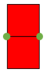
| On top of one an-other | top-left – bottom-left & top-right – bottom-right |
|
|
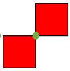
top-left – bottom-right top-right – bottom-left top-front – top-rear top-rear – top-front |
|
|
| snap points align vertically (insertion height corresponds to the dashed line) |
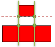
|
|
|
snap points align vertically (snap points only overwrite the insertion height if they are higher than them; for example, when inserting a wall cabinet next to a tall cabinet) |
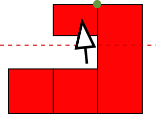
|
|
| Without snap points | snap on the next horizontal surface on which the cursor is located |

|
| Wall | article aligns automatically with back to wall |

|
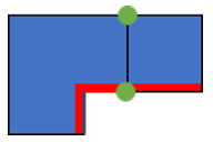
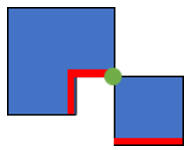
| snap points automatically snap other article snap points within a radius of 60 mm |

|

Related topics: