
Object Designer
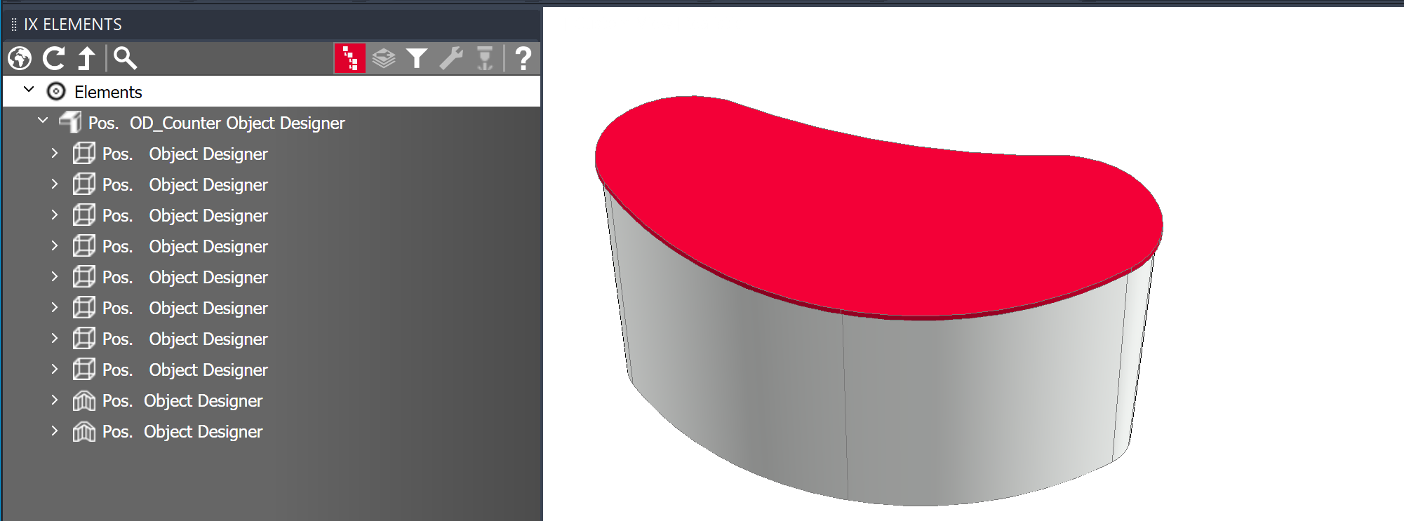
The Object Designer has also been redesigned in terms of its interface and operations. It is now fully integrated into iXplorer and, just like the Article Designer, is part of the new design.
In addition to general error corrections, new functions have been added that make it easier to work with the Object Designer and offer new options for designing objects/counters.
Operation
User interface overview
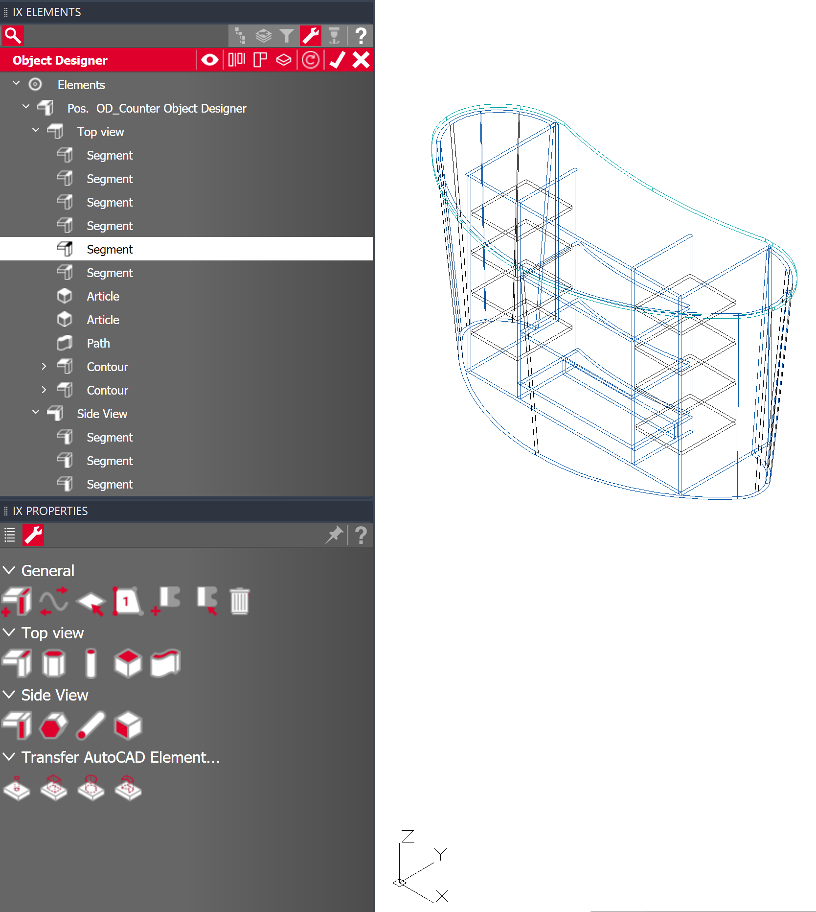
The Object Designer configuration window (Parametrics) is reached in the same way as that of the Article Designer, by creating a new Object Designer article or modifying an existing Object Designer.
|
Here, too, the interface is divided into the pallets “iX Elements” and “iX Properties”. The size and position of these pallets can be adjusted. |
|
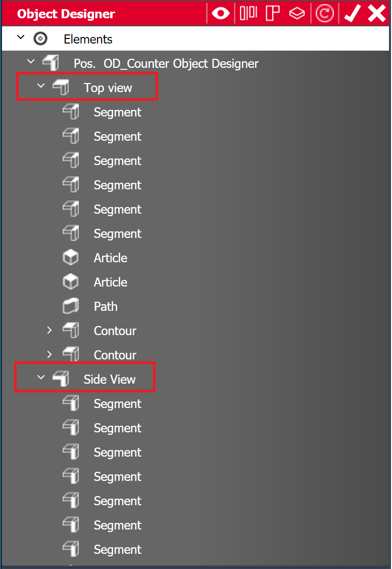
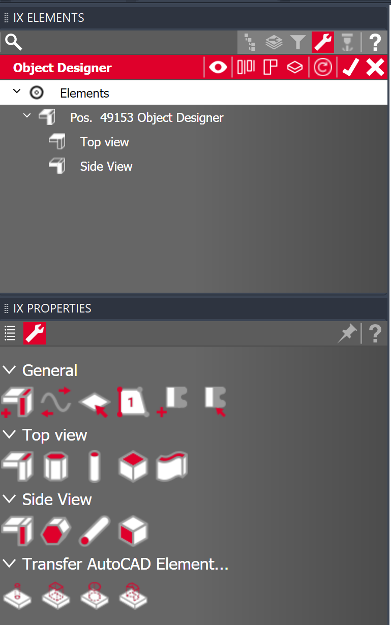
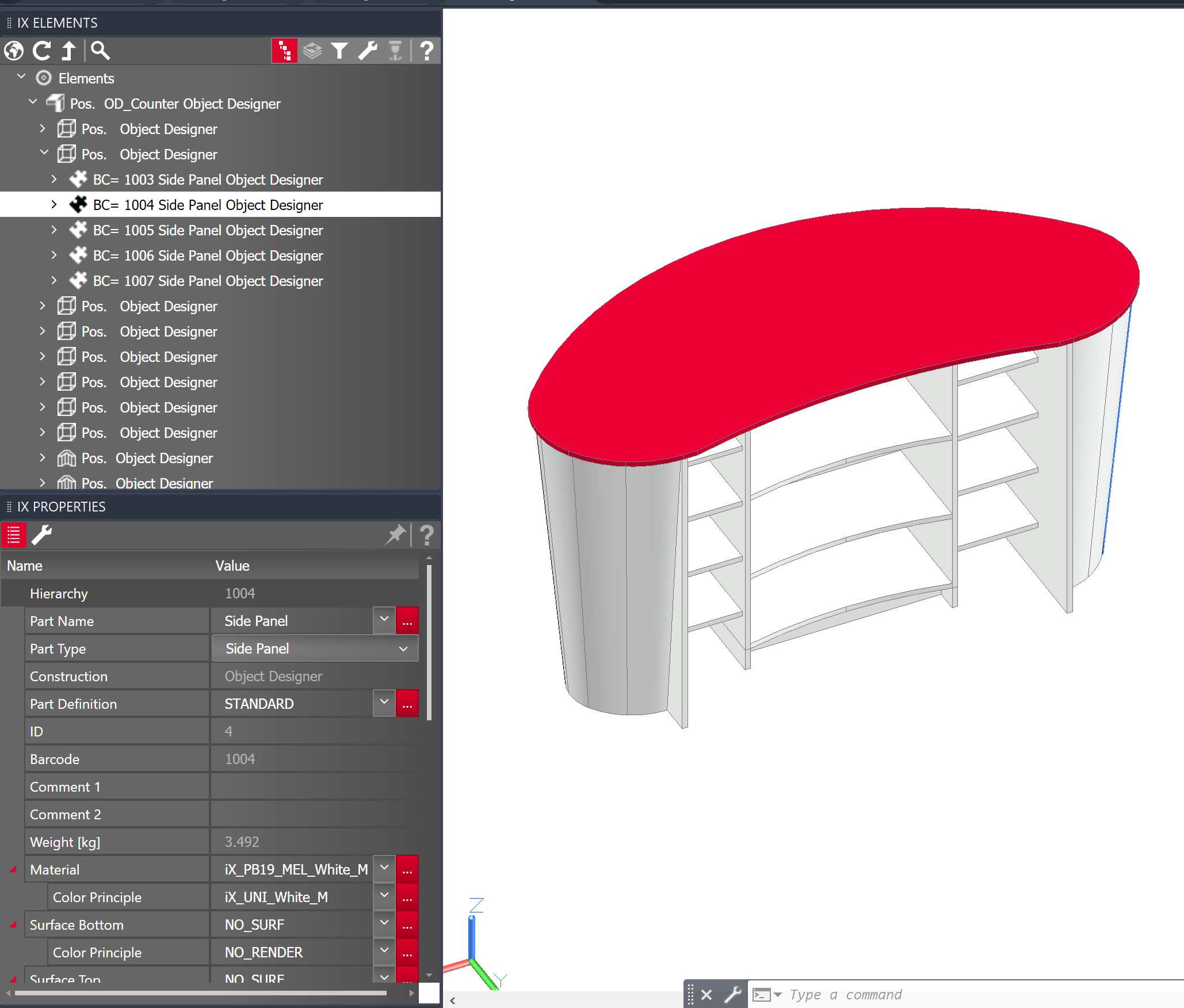
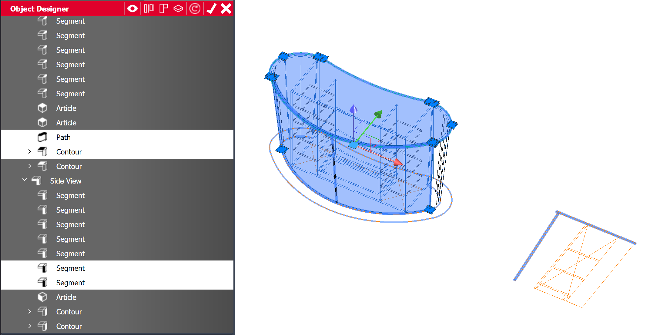
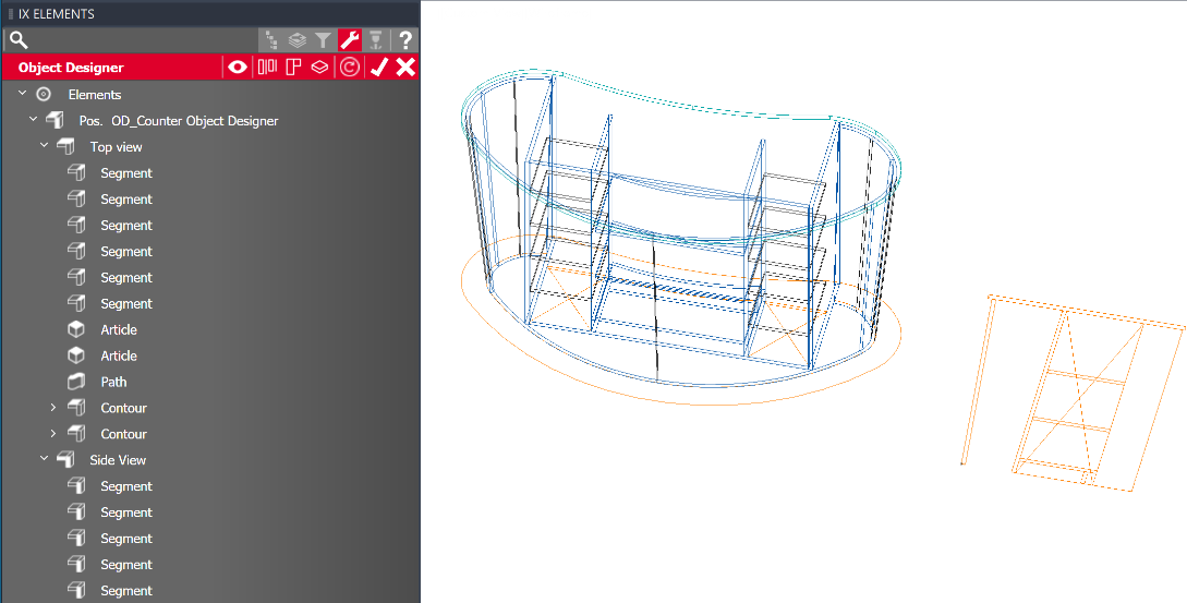
The Object Designer’s tree structure is displayed in the “iX Elements” pallet. Here, Object Designer elements (segments, contours, paths) are divided into top view and side view elements, as was the case in previous versions. The red title bar indicates that the user is in the Object Designer Parametrics. The title bar also contains additional functions for controlling visibility, updating construction, and leaving the Parametrics (Apply/Discard). |
|
|
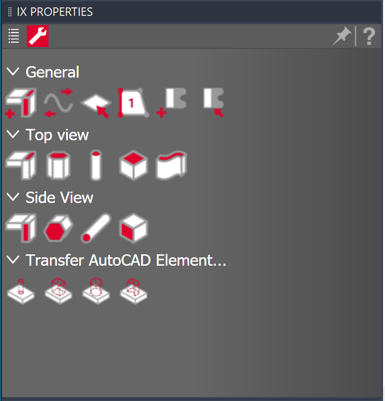
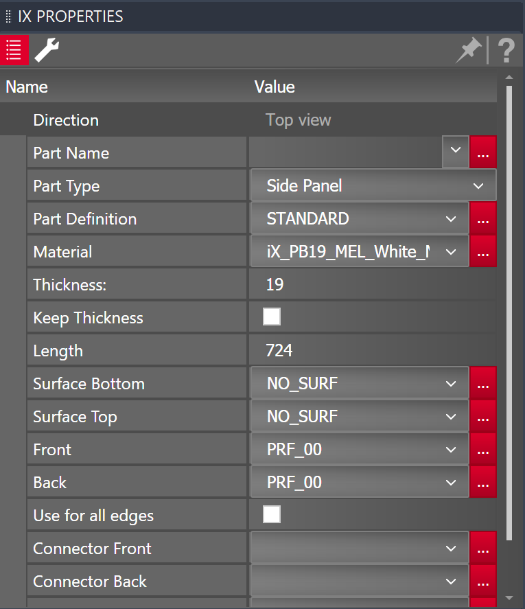
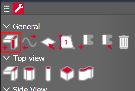
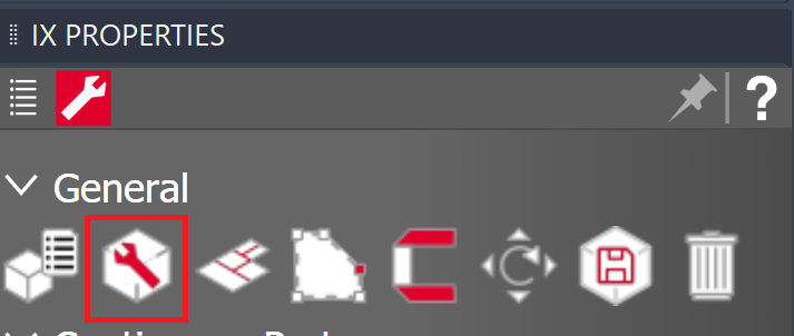
The “iX Properties” pallet features the Object Designer methods in addition to the Object Designer properties. The tab at the top of the pallet is used to switch between the methods and the properties.
Removing the Object Designer methods from the ribbon menu and adding them to the Object Designer Parametrics helps to avoid errors, as the methods are now only available when an Object Designer is being modified. |
Creating an Object Designer
The following describes how to create a new Object Designer article using the new interface and workflow.
Create new Object Designer
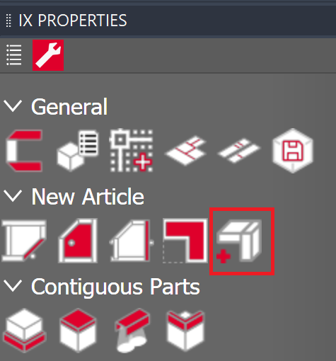
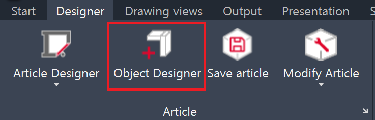
First create a new Object Designer article. Do this using the ribbon menu or via the iXplorer methods.
|
|
|
|
imos automatically switches to the Object Designer Parametrics.
|
Load an architectural drawing or draw a template
Object Designer articles are usually based on a template drawing consisting of a top view and a side view. This may be an existing architectural drawing imported via the function DWG In, or a template that the user has drawn in imos.
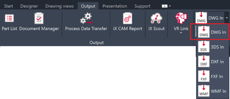
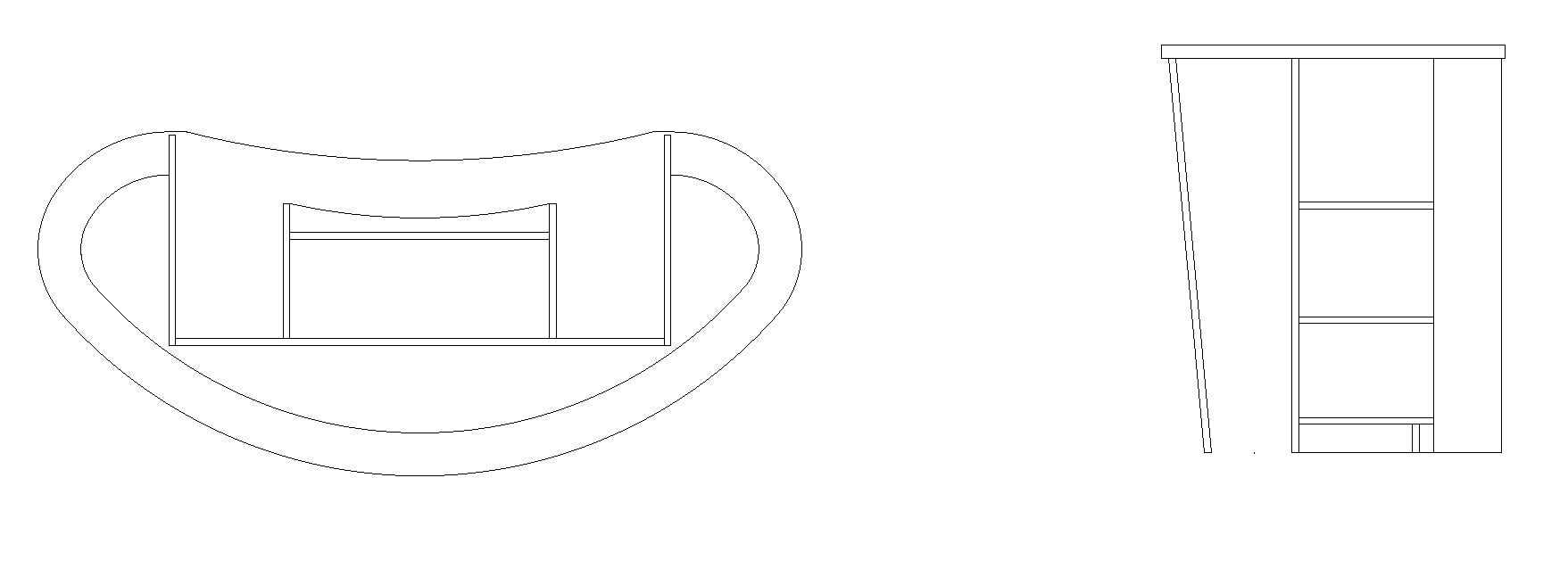
Select initial entities
Once the template drawing is imported or created, it has to be defined as such. This is done using the method “Select initial entities”.
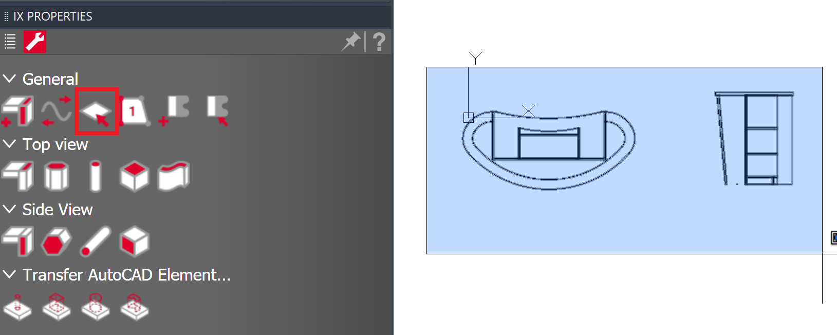
This connects the template with the current Object Designer and allows it to be shown or hidden using the visibility controls.

Showing and hiding the template can be helpful during the design process in order to achieve greater clarity. In addition, the template is now automatically hidden when Parametrics is closed.
Create top view and side view elements
Top view and side view elements can be created based on the template drawing.
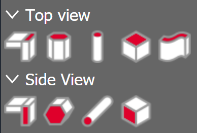
|
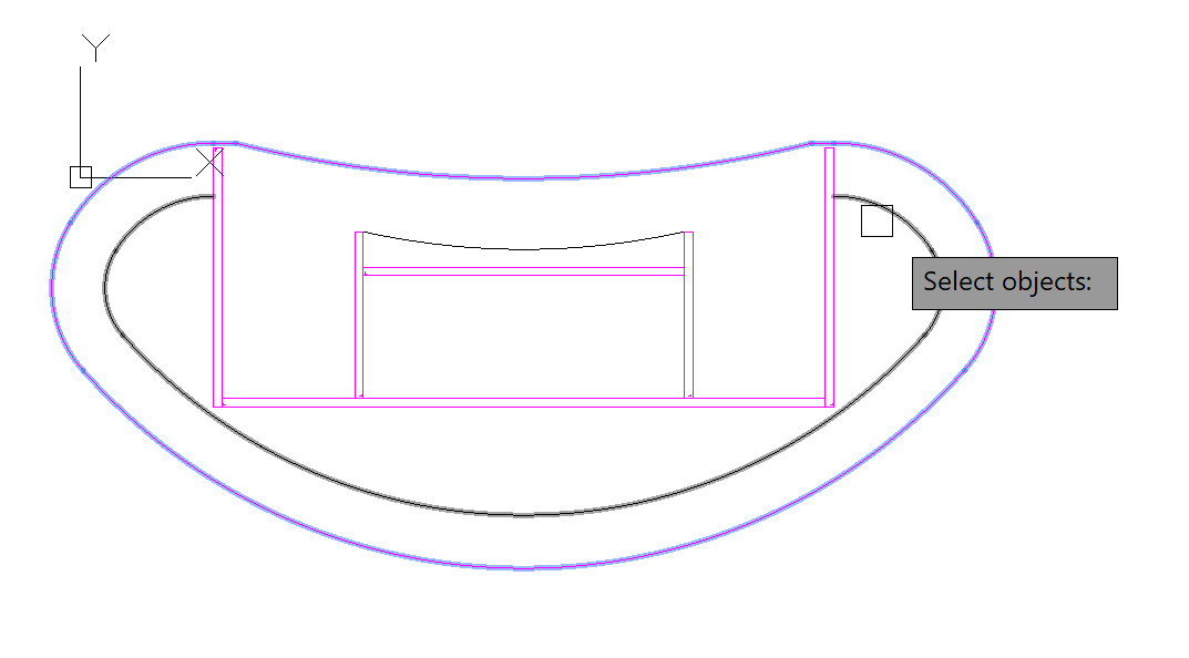
|
Tip: Within the Object Designer Parametrics, you can click <SPACE> to use the AutoCAD function “Repeat Command”. This means there is no need to access the method pallet again and again in order to execute the same function.
Top view and side view elements can also be shown or hidden using visibility controls. They are automatically hidden when Parametrics is closed, just like initial entities.

Delete top view and side view elements
There are three ways to delete top view and side view elements.
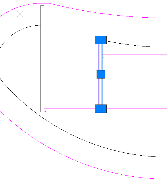
|
By selecting the desired element in CAD and pressing <DEL> |
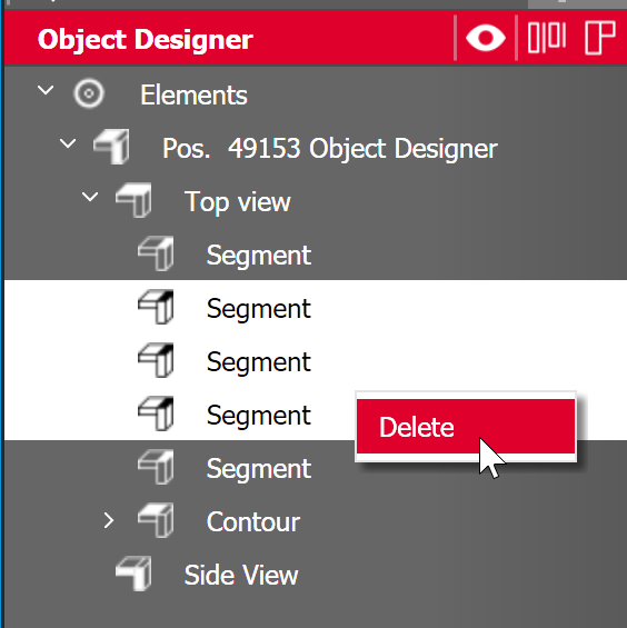
|
Using the menu in the tree |
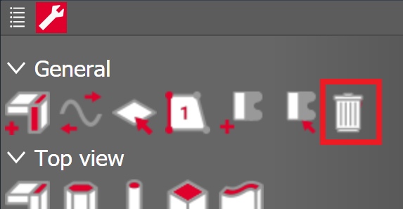
|
Using the “Delete” method |
Set element properties
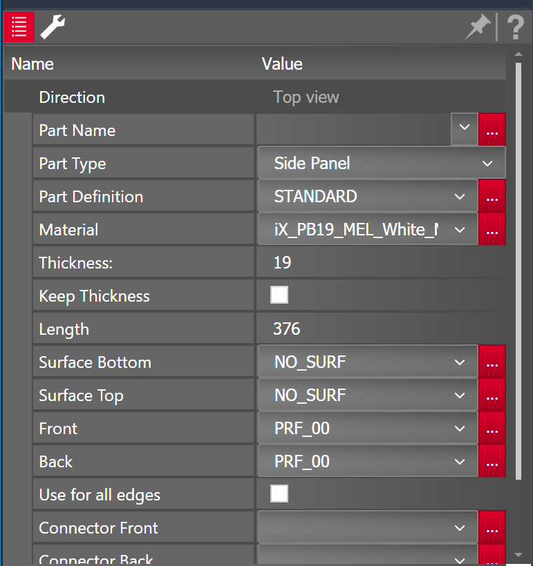
|
Object Designer element properties can be set as before in the “iX Properties” by switching to the relevant tab.
|
Create parts
Parts are created from top view and side view elements as in previous versions of the program. Select the elements from which parts are to be generated by calling the method “Parts from two Views” in CAD.
|
|
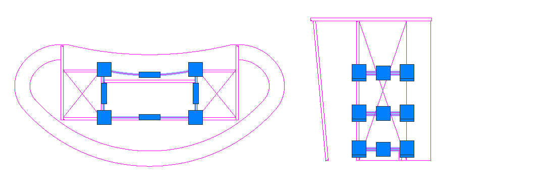
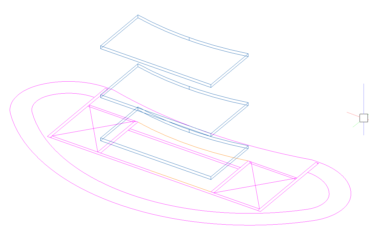
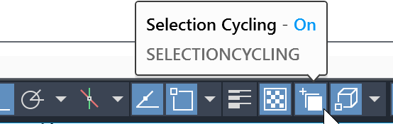
Tip: It makes sense to hide the initial entities at this point, in order to simplify selection of the top view and side view elements. It is also a good idea to activate the AutoCAD function “Selection cycling”. This makes it easier to select the desired objects even if there are other objects superimposed on them.

|
|
Just like other Object Designer elements, parts can be shown or hidden using the visibility controls.

Refresh construction
To ensure that changes to Object Designer element properties, positions, or forms affect parts that have already been generated, you have to refresh the construction. The “Refresh” function is located in the Object Designer Parametrics red title bar and therefore always available. One click on the button refreshes the Object Designer article.

Closing Parametrics
If the user wishes to close the Object Designer, they can do so by clicking on Apply or Discard in the Parametrics.

They will then once again return to CAD.
Modify Object Designer
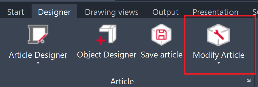
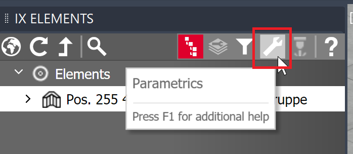
Object Designers are modified in the same manner as Article Designers. There are three ways to do this:
|
|
|
|
|
|
Save Object Designer
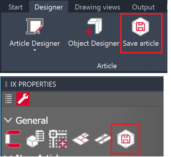
The introduction of the new Save article dialog means that an Object Designer article is saved just like any other type of article.
To save an Object Designer article, either call the method from the ribbon menu and select the Object Designer article in CAD, or select the Object Designer in the tree and call the Save function via the methods.
The Object Designer is then available in the main data or the Article Center.
New Object Designer functions
Undo changes
Changes within the Object Designer Parametrics can be discarded when exiting the Parametrics by clicking “Discard”.

This is also the case for the Article Designer or the Contiguous Parts Parametrics. A backup of the Object Designer data is created when you enter the Object Designer Parametrics. If you close the Parametrics by clicking “Discard”, this backup will be restored, reversing any changes.
Note: This does not apply to pure AutoCAD objects (e.g. polylines) drawn, modified, or deleted in the Parametrics, as they are not part of the Object Designer data.
Select
The user can select Object Designer elements in CAD or via the tree. The elements are then highlighted in the tree and/or in CAD.
If one or more parts are selected in CAD, then the top view and side view elements responsible for creating the part will be selected in the tree and in CAD. This allows the user to quickly check and adjust the properties of the relevant Object Designer elements.
Object Designer element visibility
One new feature in terms of templates, top view, and side view elements is that they now react within the Object Designer instead of globally. If an order contains several Object Designer articles, then when the Object Designer is modified, only those elements that belong to that specific Object Designer will be shown/hidden.
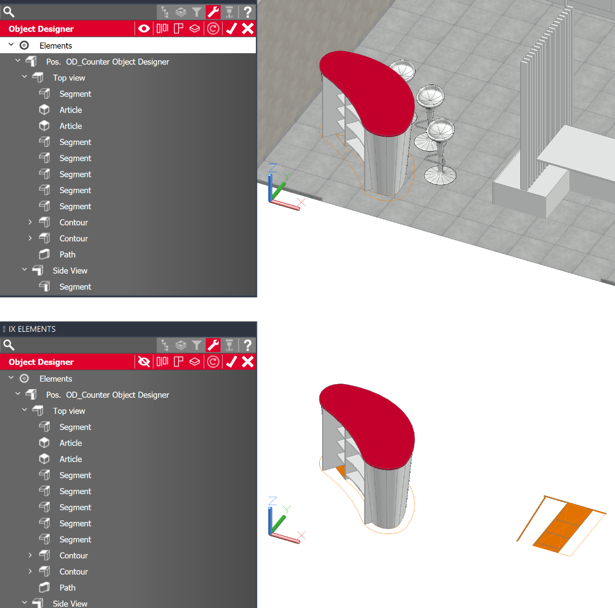
When entering and exiting the Parametrics, initial entities, top view and side view elements are automatically shown and hidden. They are only visible within the Parametrics. This improves clarity when viewing the order and the layout.
Within the Parametrics, Object Designer element visibility is controlled using three buttons in the red title bar. They are easily accessible and always available.
- Show/hide initial entities
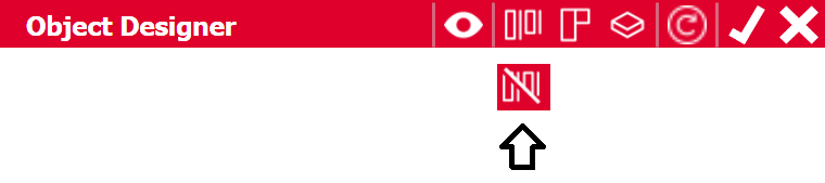
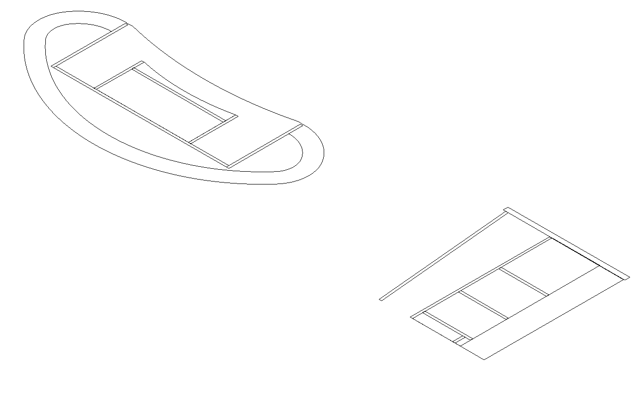
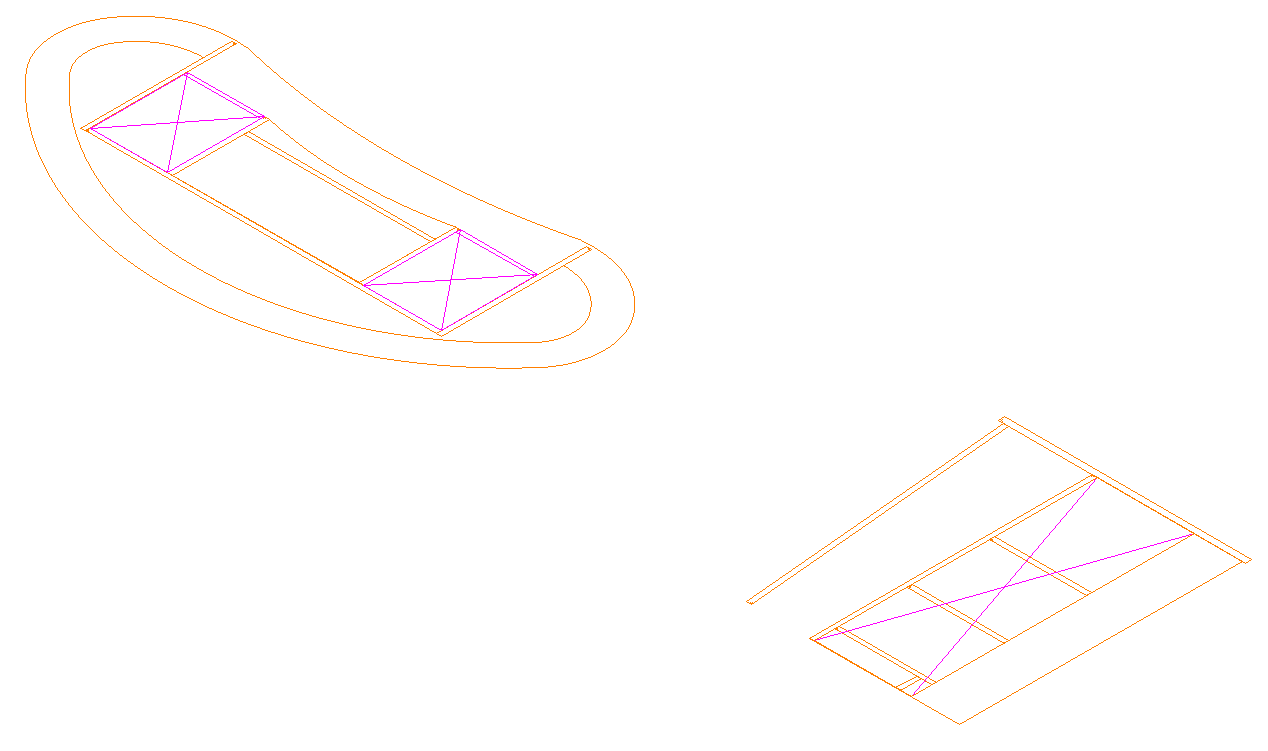
- Show/hide top view and side view elements
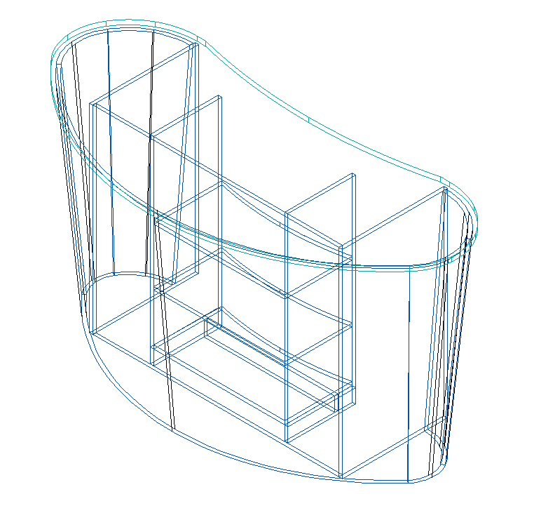
- Show/hide parts
Isolating the Object Designer
Just as with the Article Designer, the Object Designer offers a function for isolating the article. This means the user can maintain an overview even when working with complex layouts and concentrate on the task at hand.
Array function (_ARRAY)
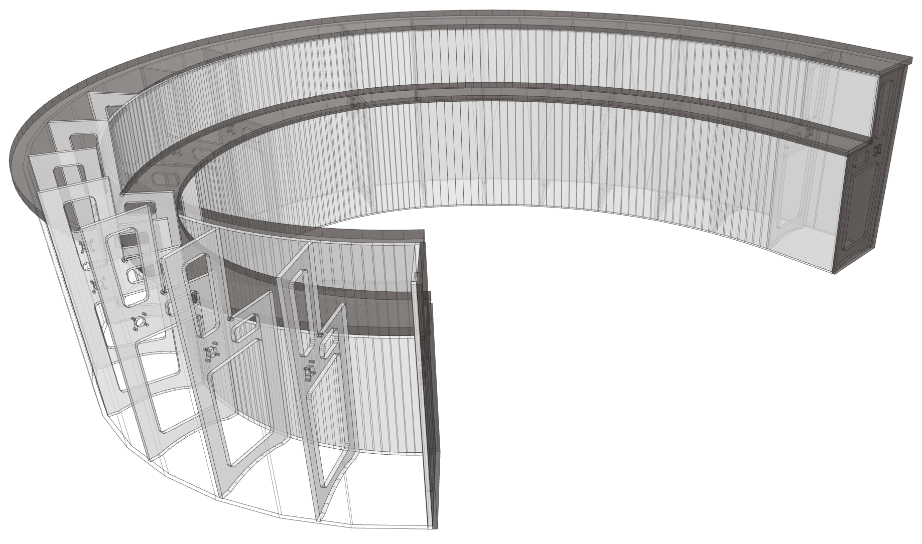
The program now supports the AutoCAD function _ARRAY in connection with Object Designer elements. This makes it possible to create many top view or side view elements quickly in a single operation.
This is particularly helpful for objects designed with studs constructions (e.g. counters or trade fair booths).
Notes:
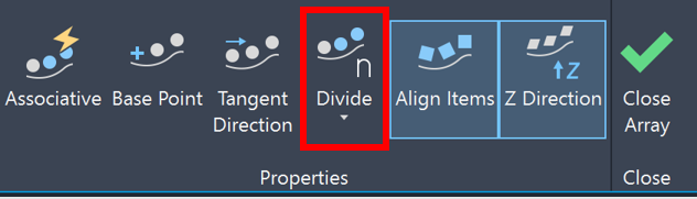
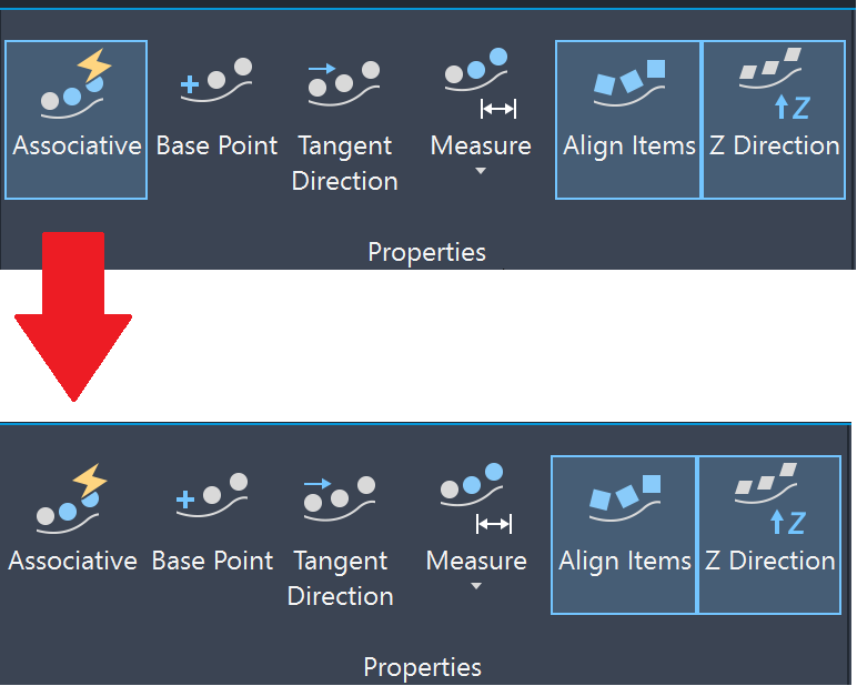
- When using the _array function, the associative option must be turned off to ensure that the function works normally within imos.
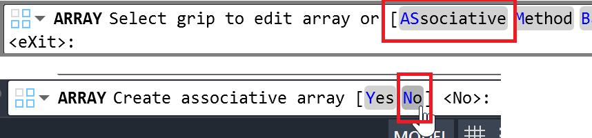
- The “Array” interface looks different depending on whether or not a full version of AutoCAD is in use. The AutoCAD full version offers setting options in the ribbon menu that are otherwise only available via the AutoCAD command line.
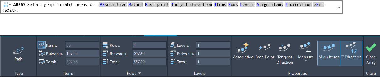
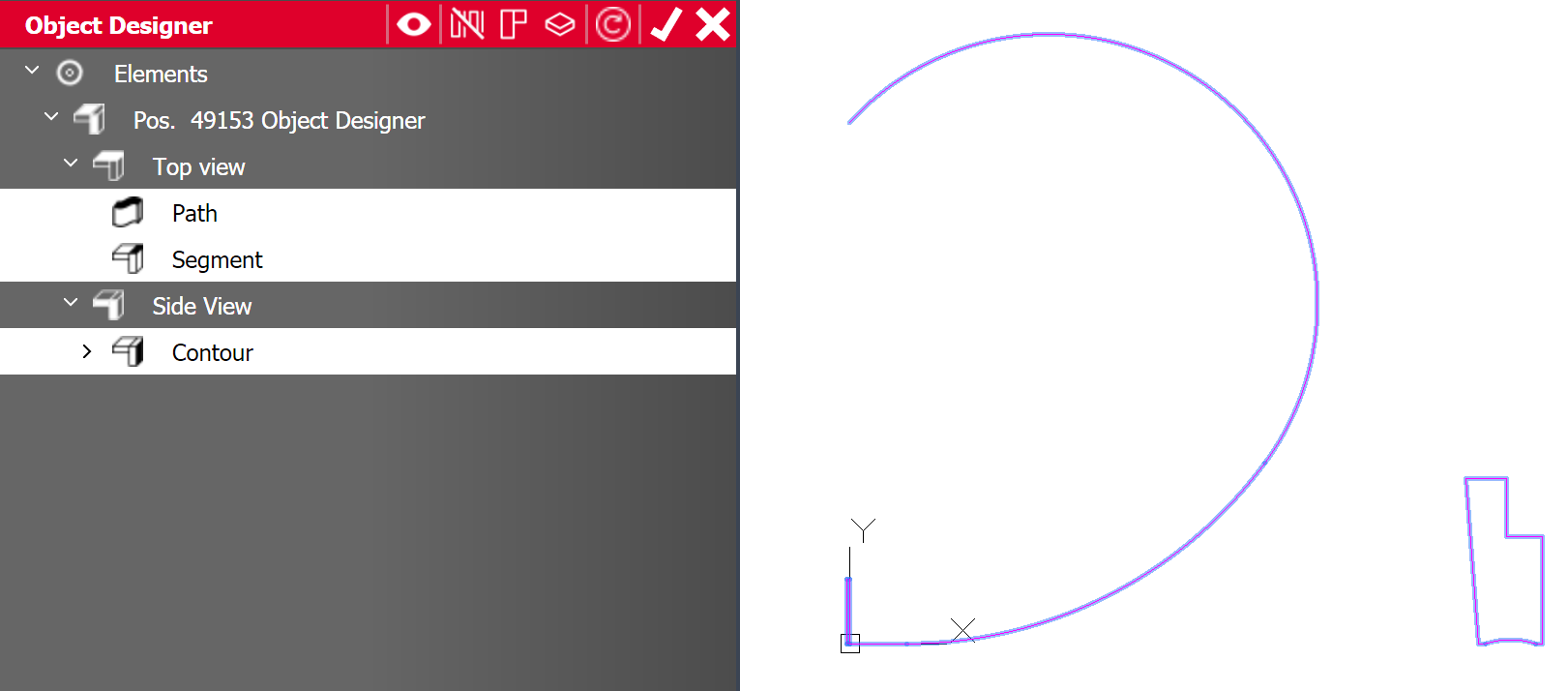
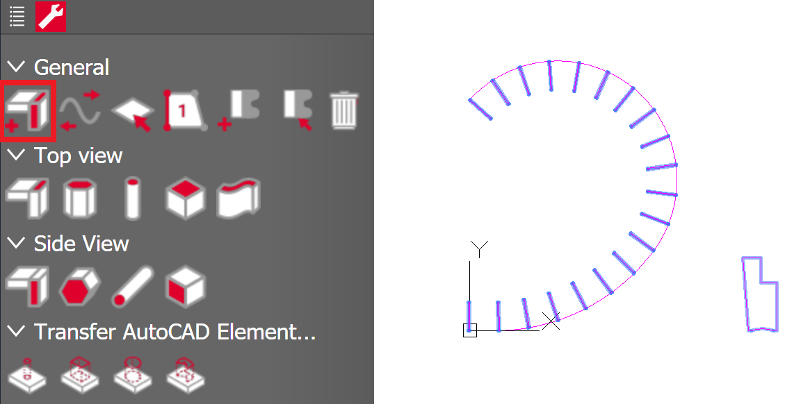
The following describes how to use the “Array” function with Object Designer elements. This example uses an extrusion path, a top view segment, and a side view contour.
|
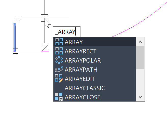
Enter the _ARRAY command. Select the object to be copied, in this case the top view segment. |
|
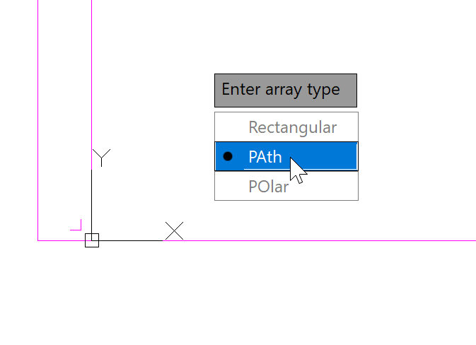
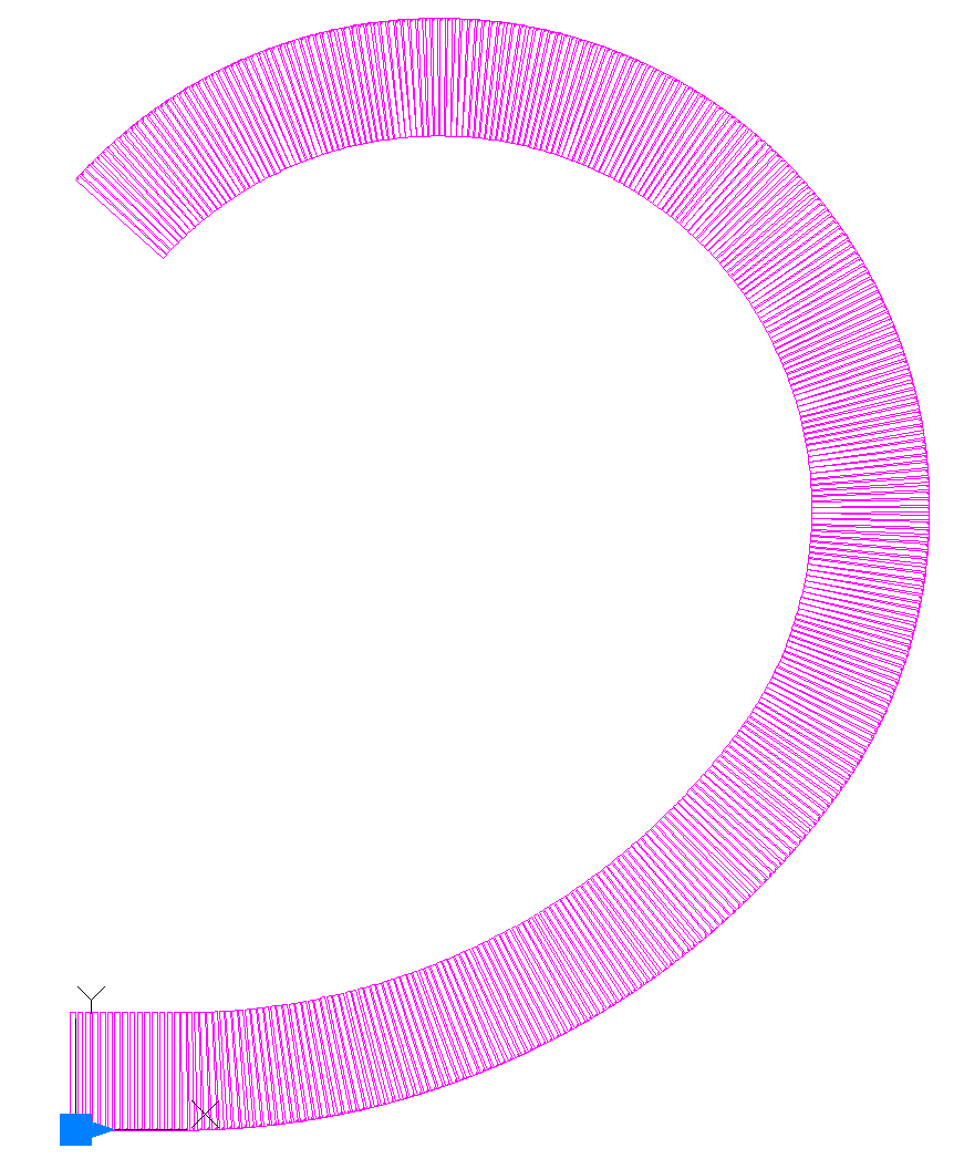
Select the “Array type” (rectangular, path, or polar). For this example, select “Path”. Select the extrusion path. |
|
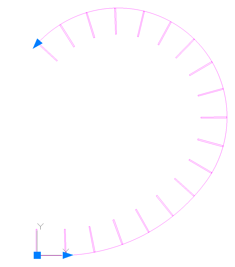
n copies of the segment will be created based on the “Array” settings. The settings can be adjusted via the command line options.
If a full version of AutoCAD is in use, these settings can also be changed in the ribbon menu.
|
|
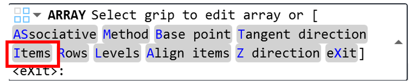
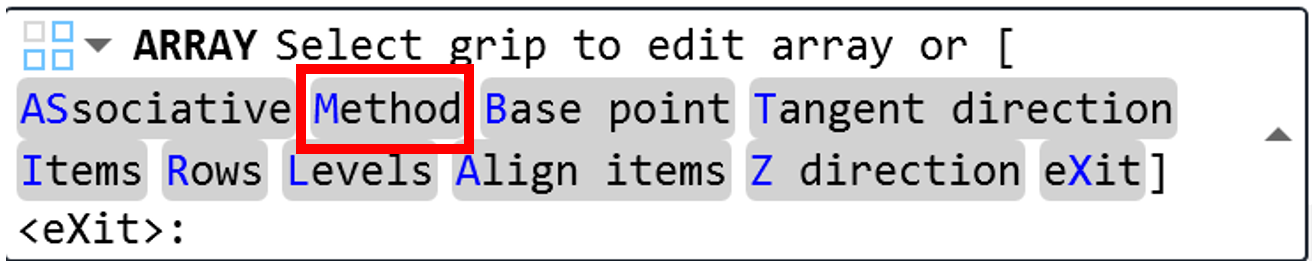
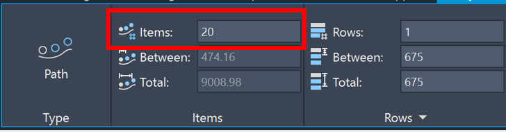
In this example, we want to create 20 segments that will be distributed evenly across the path. Adjust the “Array” settings as follows: Command line options:
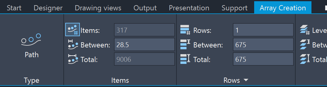
Ribbon menu:
Note: As already mentioned above, it is important to deactivate the associative option in the “Array” settings.
Command line options:
Ribbon menu:
|
|
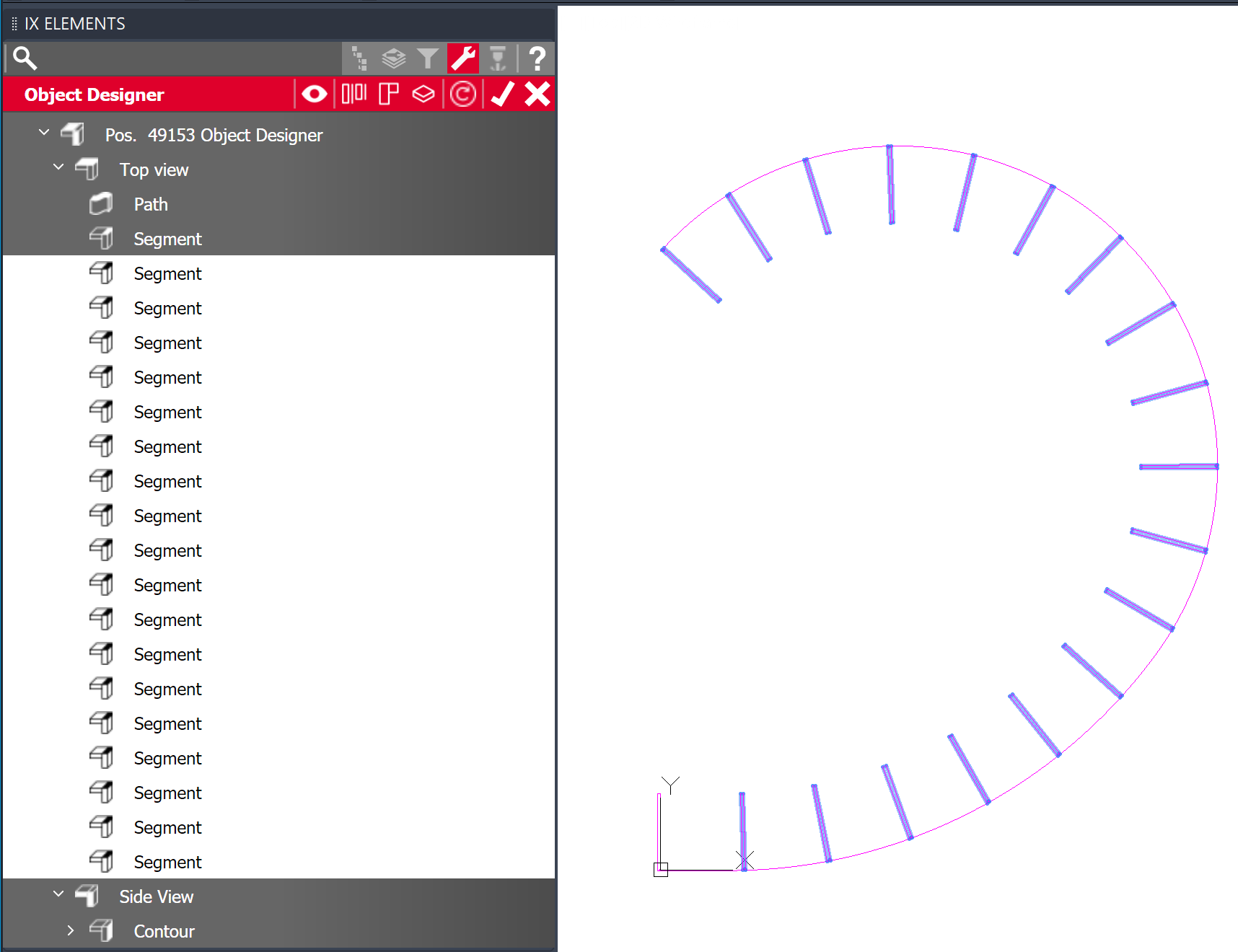
The 20 segments will be created once the “Array” command is closed.
The tree structure will be updated accordingly: New top view segments have been created. |
|
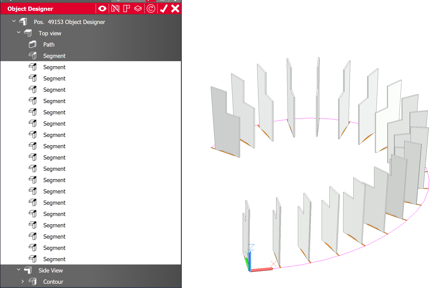
In the next step, you can generate the imos parts using “Parts from two Views”.
|
|
|
|




Machining in the Object Designer
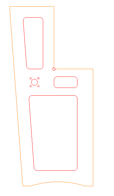
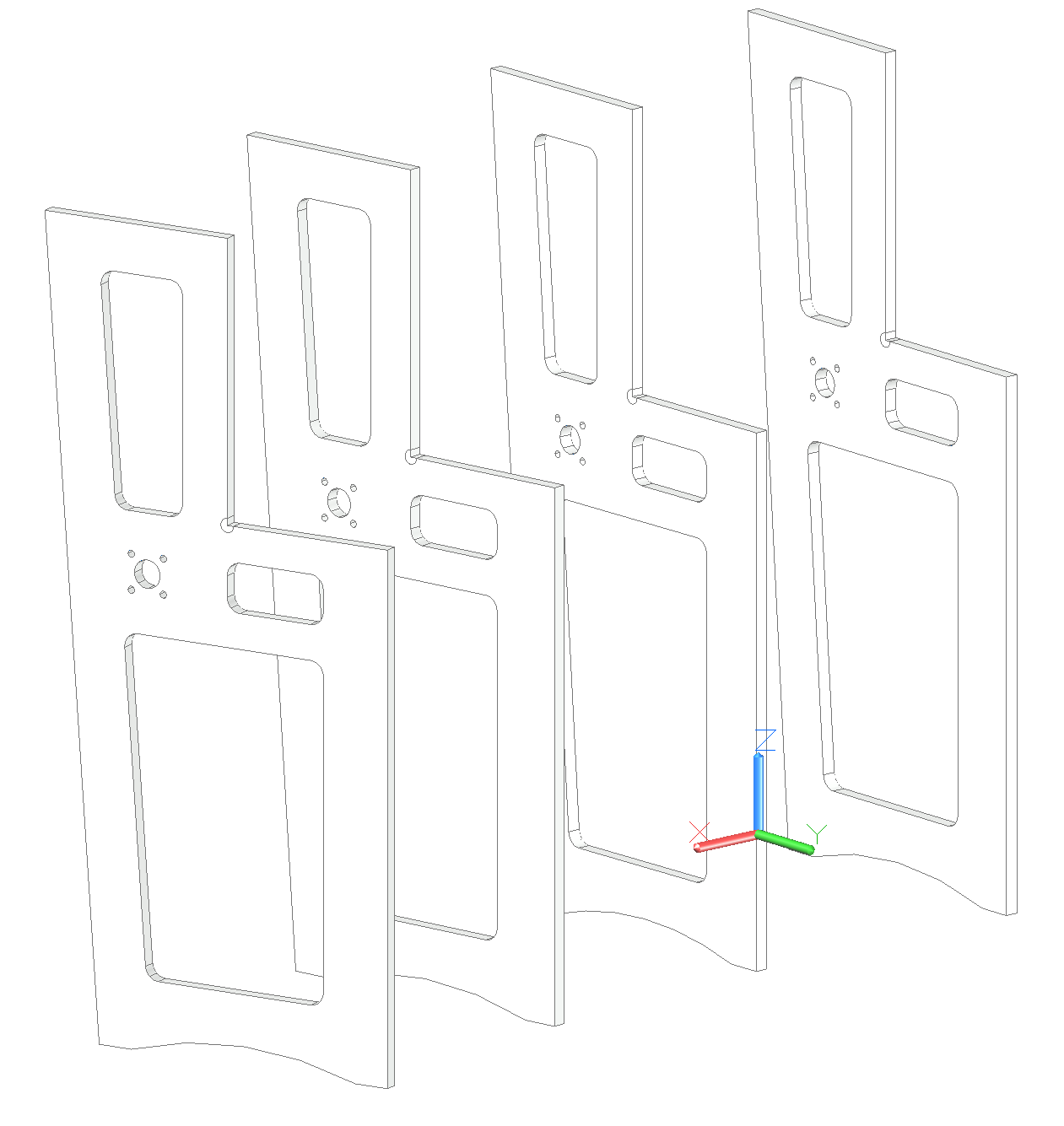
In iX CAD 2021, you can create machinings in the top view or side view contours. The machinings transfer to all Object Designer parts created with the top view or side view contours. Subsequent modifications can also be made to the machinings, which will take effect once the construction is refreshed.
Tip: The machinings are also kept in OD parts created with the Array function.
|
|
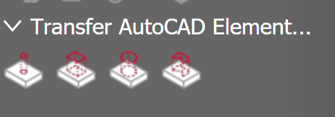
The function “Transfer AutoCAD Elements” has been expanded in the Object Designer method pallet for assigning machinings:
|
|
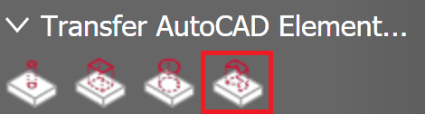
|
Select the desired method, in this case “Polyline as an inner contour”. |
|
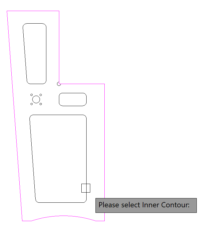
In CAD, select the Polyline to be transferred as an inner contour. |
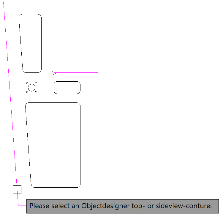
|
Select the top view or side view contour to which the machining is to be assigned.
|
|
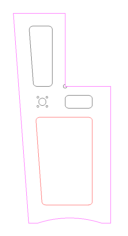
The inner contour will become an imos machining. Machinings are marked with red lines. |
|
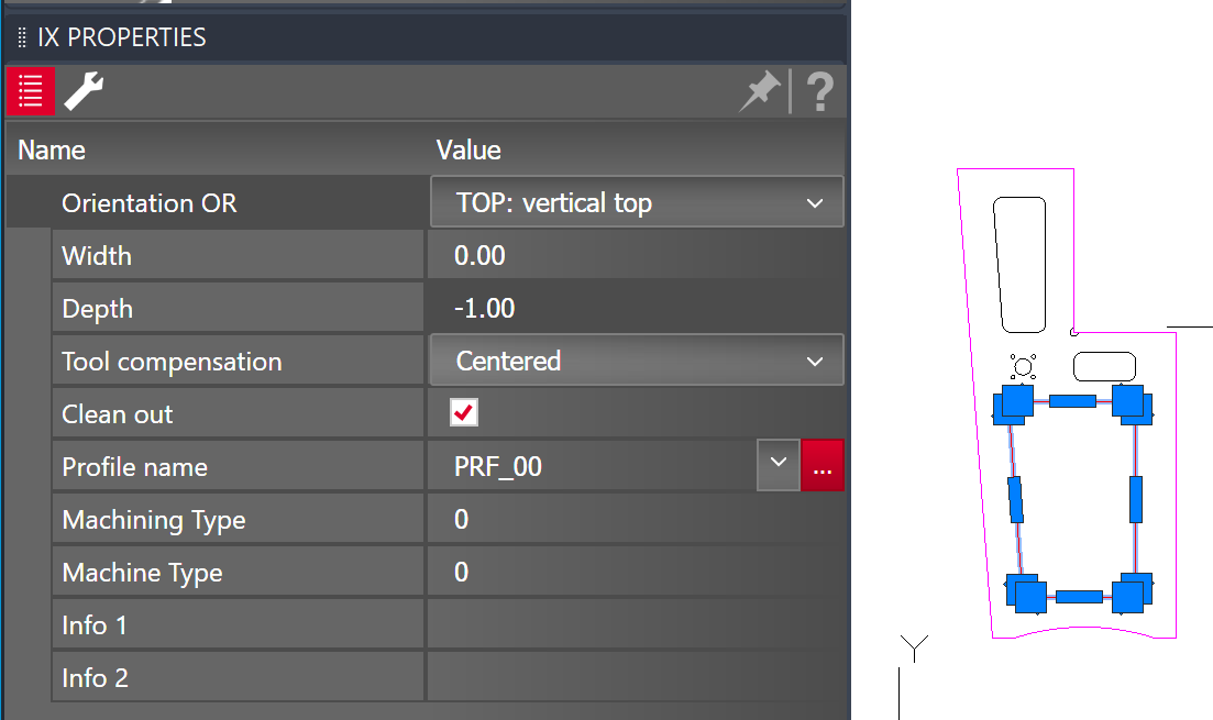
The machining properties can be adjusted under the properties tab. |
|
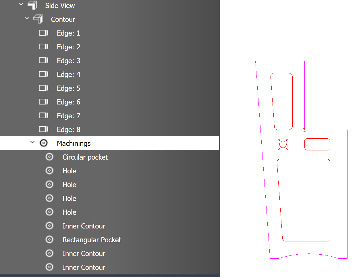
Repeat this process with the remaining machinings to be transferred. In the tree, the machinings will appear underneath the top view or side view contours.
|
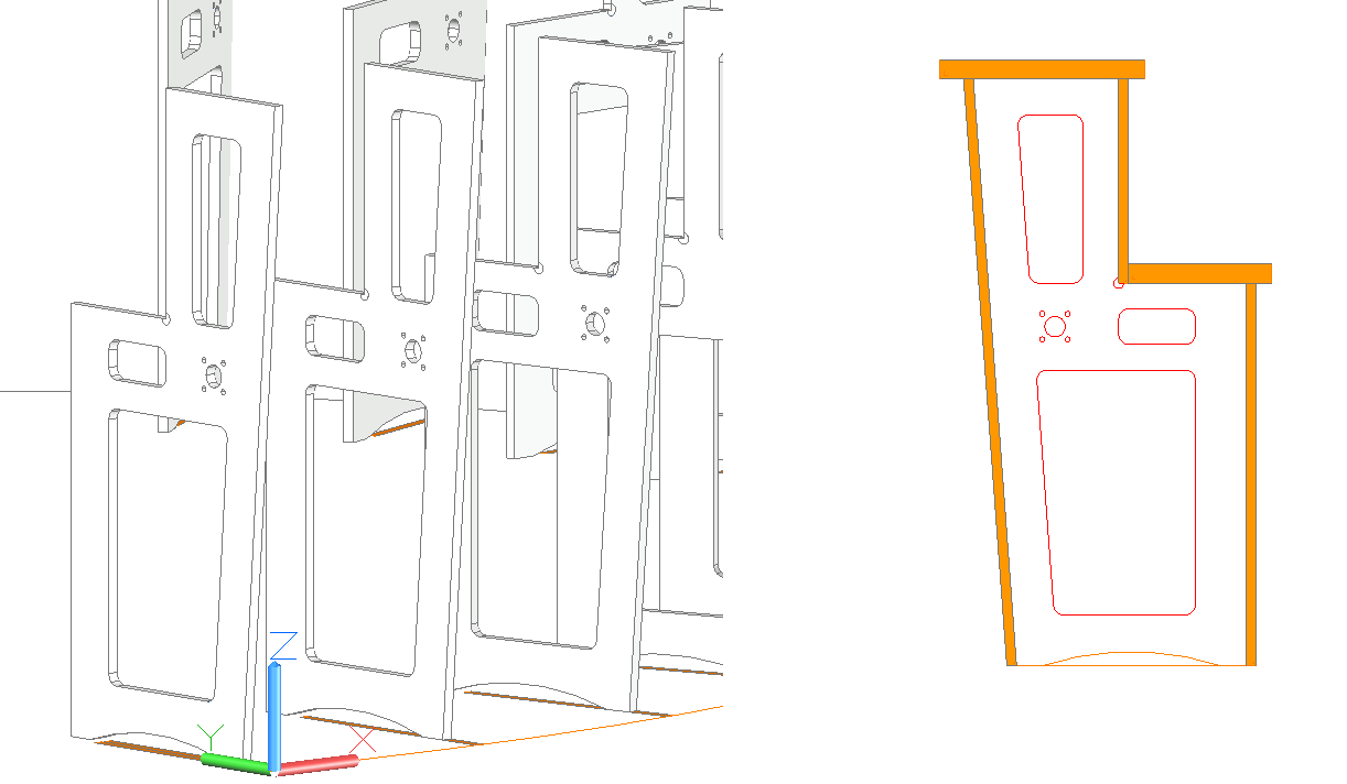
|
As soon as you create the parts using “Parts from two Views”, the machinings will be imported in accordance with the specifications. |
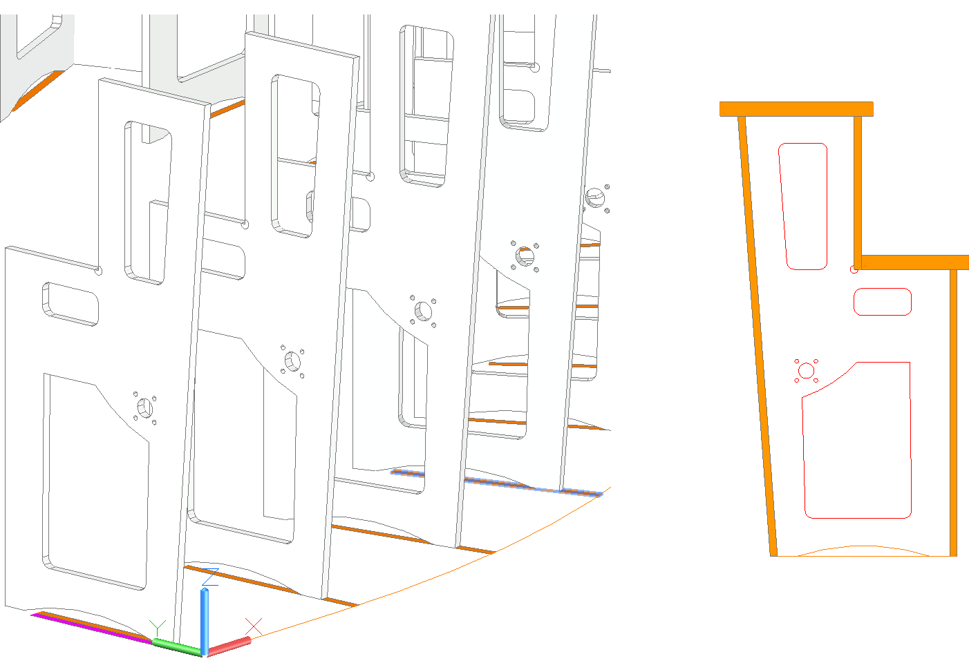
|
If you change the properties, form, or position of a machining later on, it will take effect once the construction has been refreshed. |
Edge sequences and direction of contour
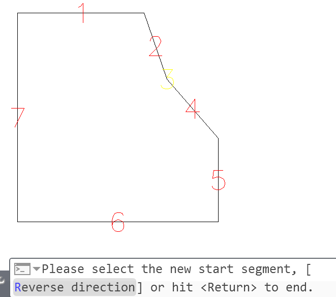
It is easy to adjust the edge sequence and direction of contour at a later date using the method “Edge sequence”. This is particularly helpful in the Object Designer environment, where external architectural drawings are often used as a template. These templates are not always drawn in a manner that is optimal for use with imos.
|
The method “Edge sequence” is located in the Object Designer methods in the “General” group. |
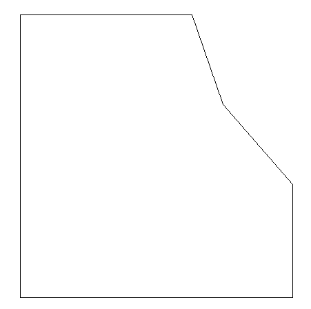
|
After calling the method, select a relevant contour (polyline) in CAD. |
|
imos will now display the contour’s edges and saw direction.
|
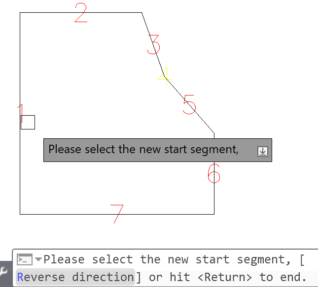
|
A simple click on a line or one of the numbers sets the edge to “Edge 1”. The other edges are adjusted accordingly. |
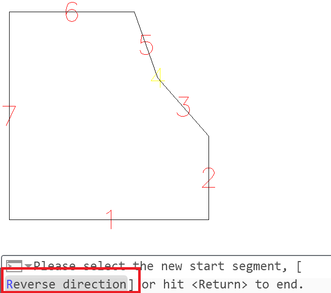
|
You can also reverse the contour’s direction using the AutoCAD command line. |
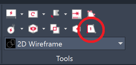
This method works with all polylines, top view, and side view contours in the Object Designer.
Tip: As this function works generally for polylines, it has also been added to the CAD toolbar. The user can thus adjust outside contours or parts contours.
Visual support (new object colors)
New colors have been introduced to top view and side view elements in order to make using the Object Designer Parametrics easier.
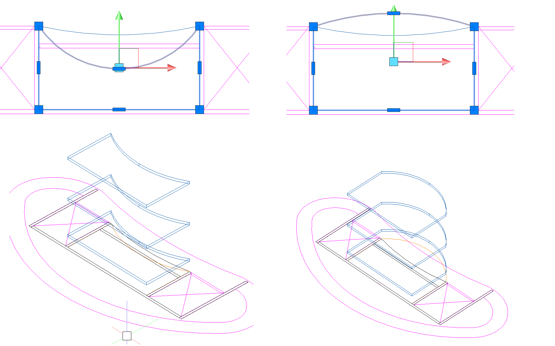
Top view and side view elements are now displayed in magenta if they have not yet been used to create a part or linked to a part. If they have been used to create a part or are linked to a part, they are displayed in orange. Machinings are displayed in red.
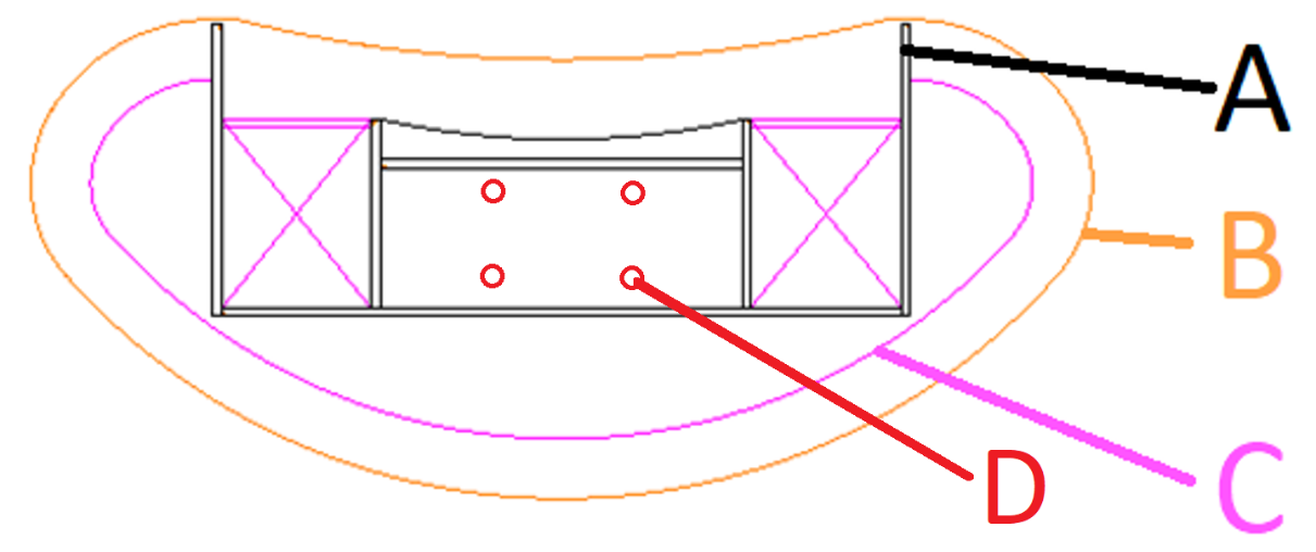
A=Initial entity
B=Top view element, linked to part
C=Top view element, not linked to part
D=Machining