Article Designer
The Article Designer has been completely redesigned for iX 2021. The focus was on providing interruption free operation without overlaying dialogs. This was achieved by moving the Article Designer into CAD. The user does not have to exit the layout to interact with the Designer.
A newly designed user interface, integration with the iXplorer interface, and standardization of operating elements and processes help keep the Article Designer simple to use and understand.Note: Existing Article Designer files can be used in iX 2021. The data model has not changed.
Operation
The redesign did require that a few small changes be made to Article Designer operation. They are explained in brief below.
Workflow
Create new Article Designer
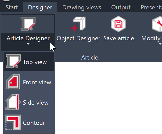
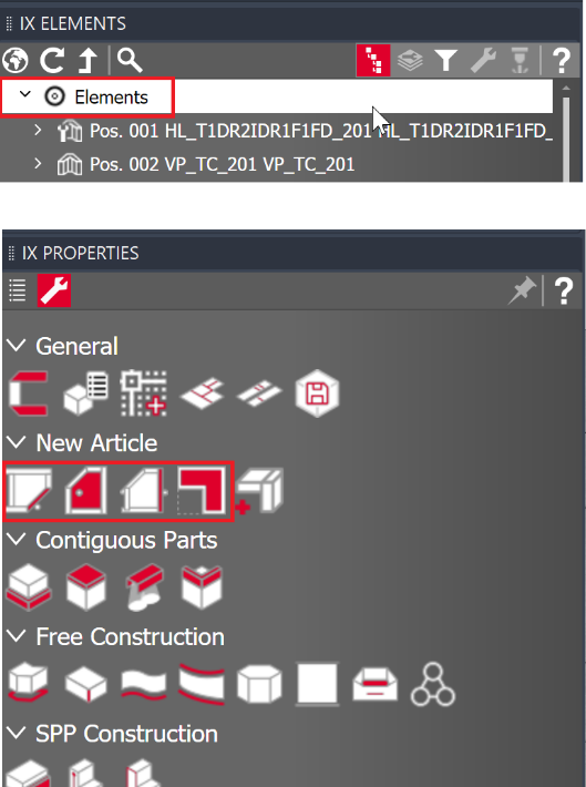
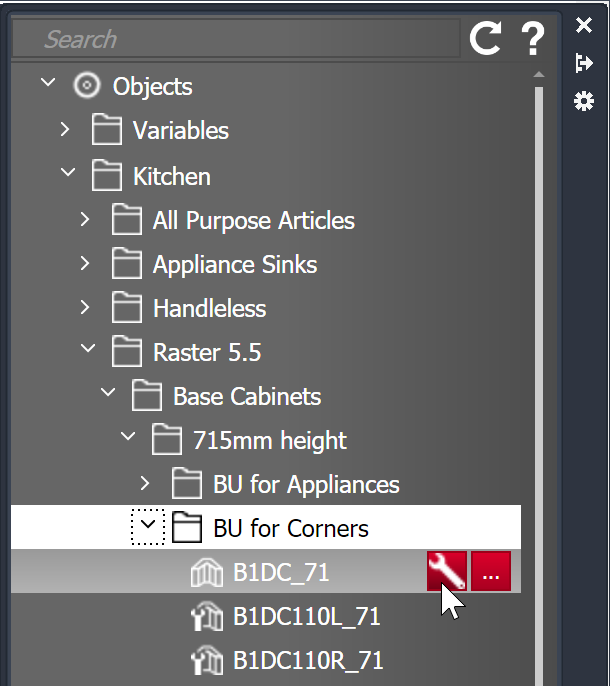
There are two ways to create an Article Designer:
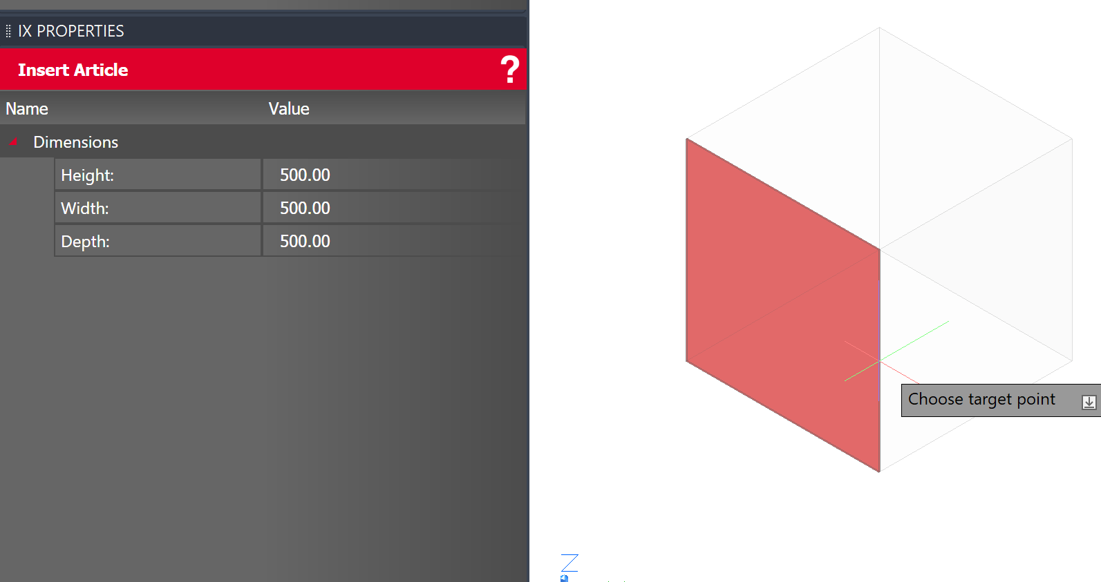
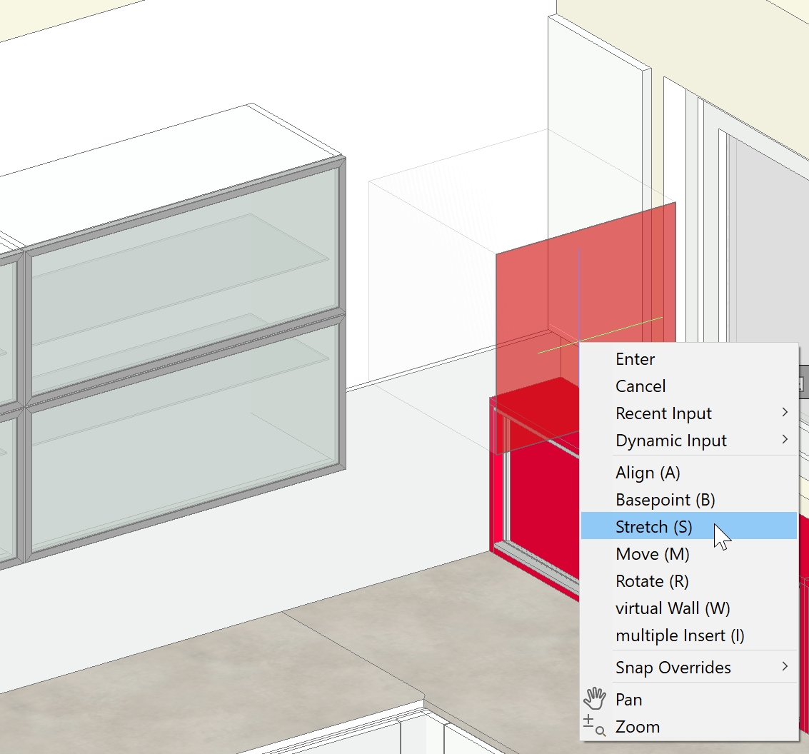
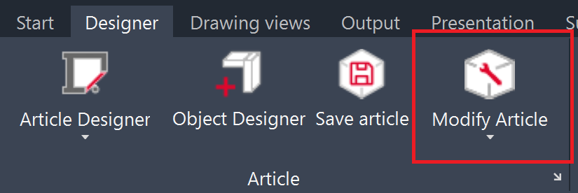
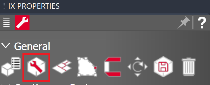
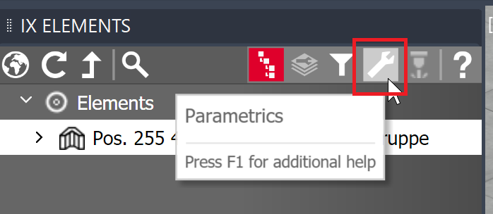
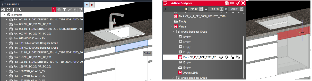
Once the box frame has been positioned in CAD, switch to the Article Designer Parametrics to begin configuring the article. Modify Article Designer in CAD There are three different ways to modify an existing Article Designer in CAD:
The part that the user selects in the tree when switching to the Article Designer Parametrics, or that the user clicked within CAD, is also selected in the Parametrics, allowing the user to quickly jump to the positions they wish to adjust.
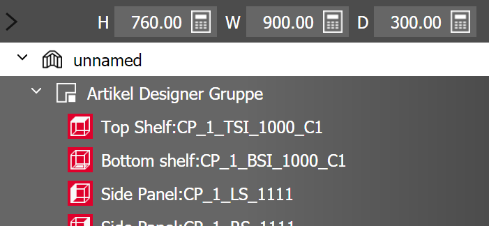
Adjust Article Designer main data
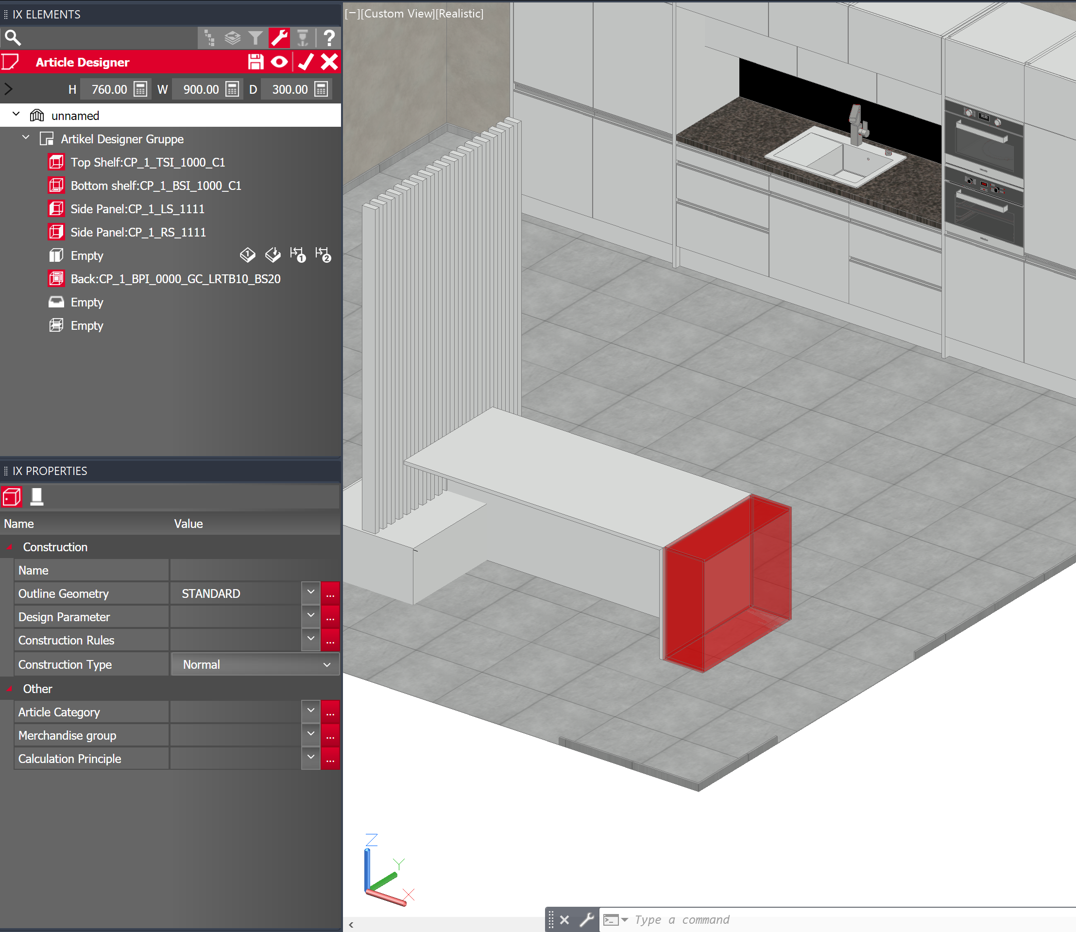
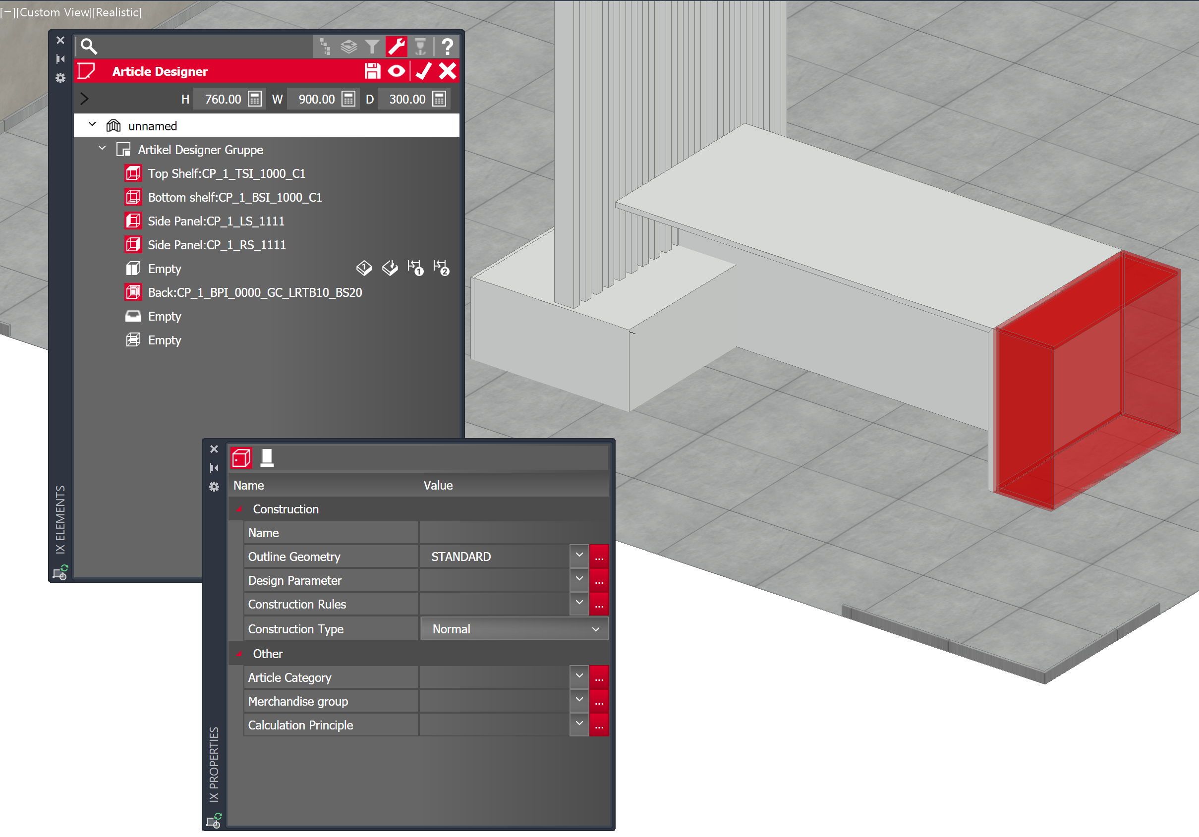
User interface overview The Article Designer Parametrics are divided into two pallets that can be positioned at will and adjusted to any size.
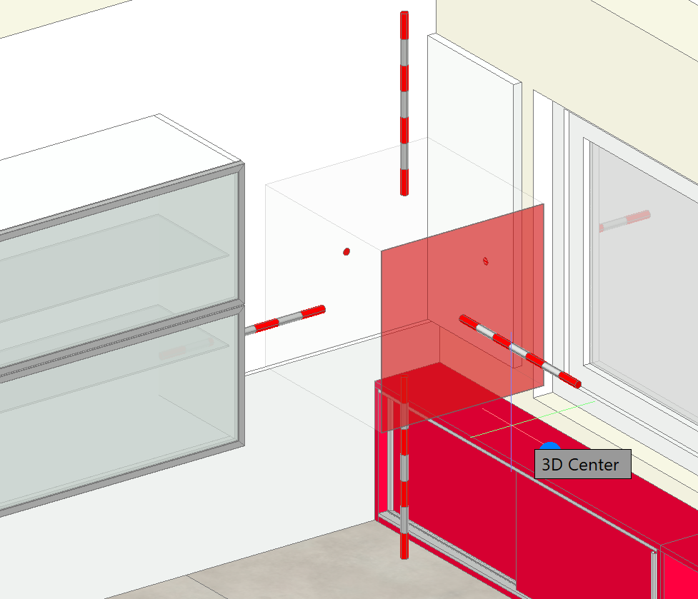
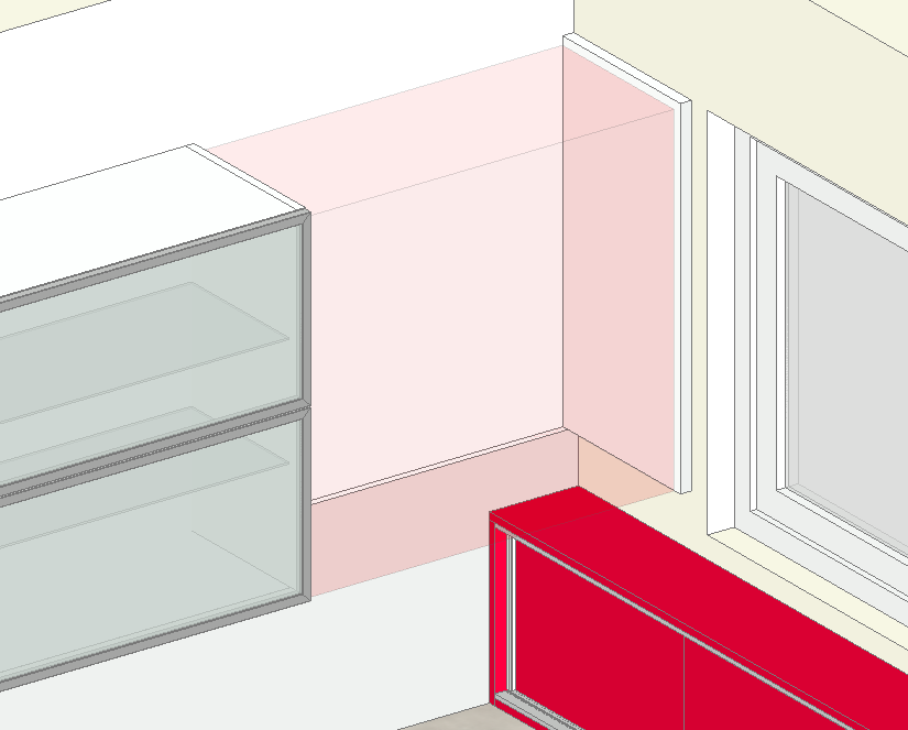
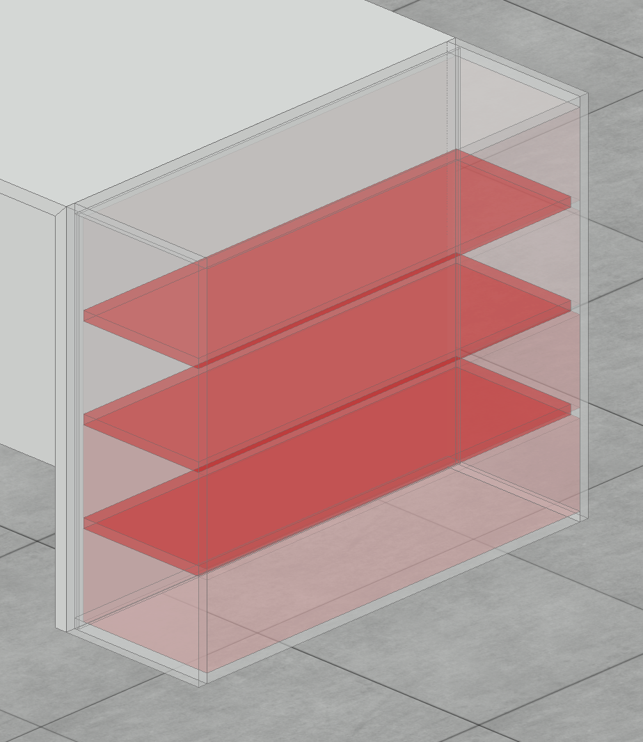
A simplified, schematic view of the current article configuration is displayed in CAD, providing direct feedback regarding changes. You can use AutoCAD functions to navigate quickly between top view, front view, or side view, and move freely in CAD.
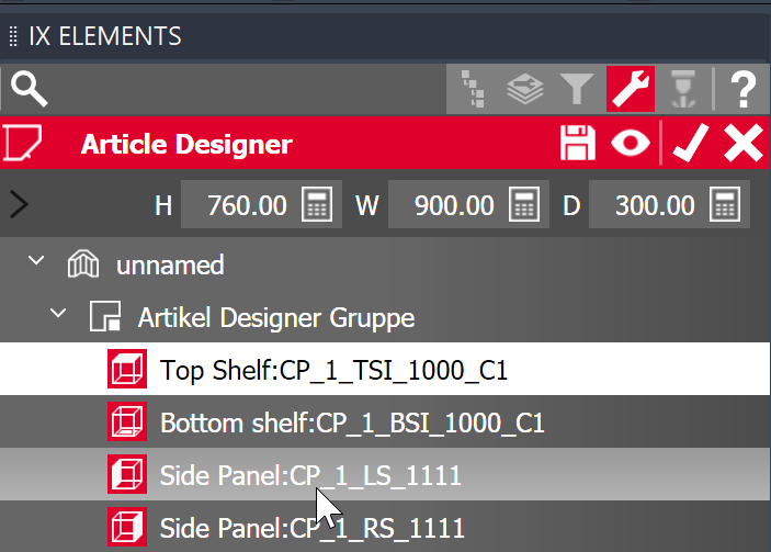
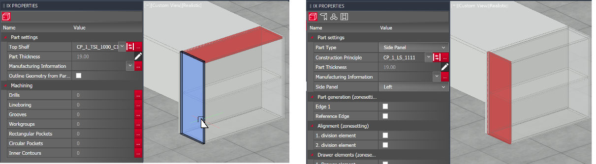
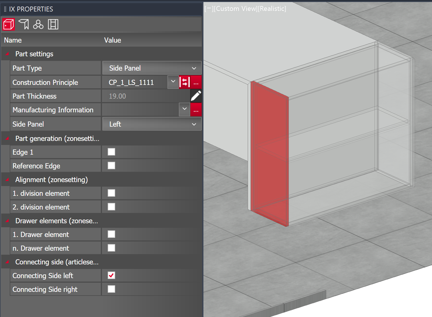
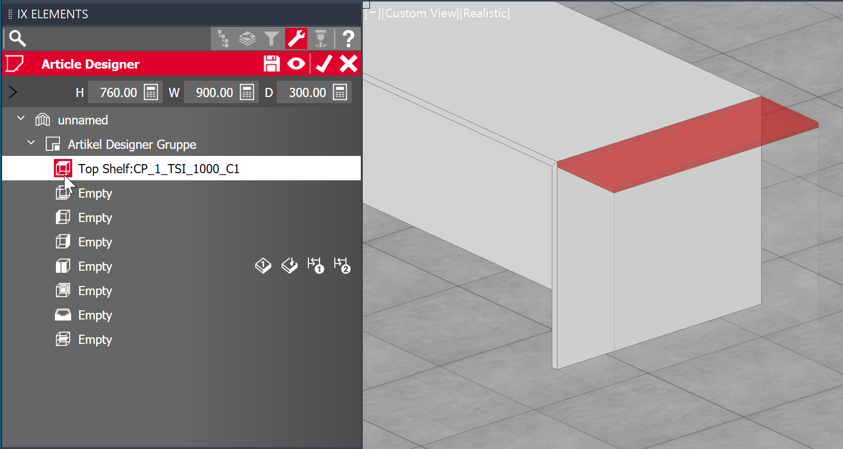
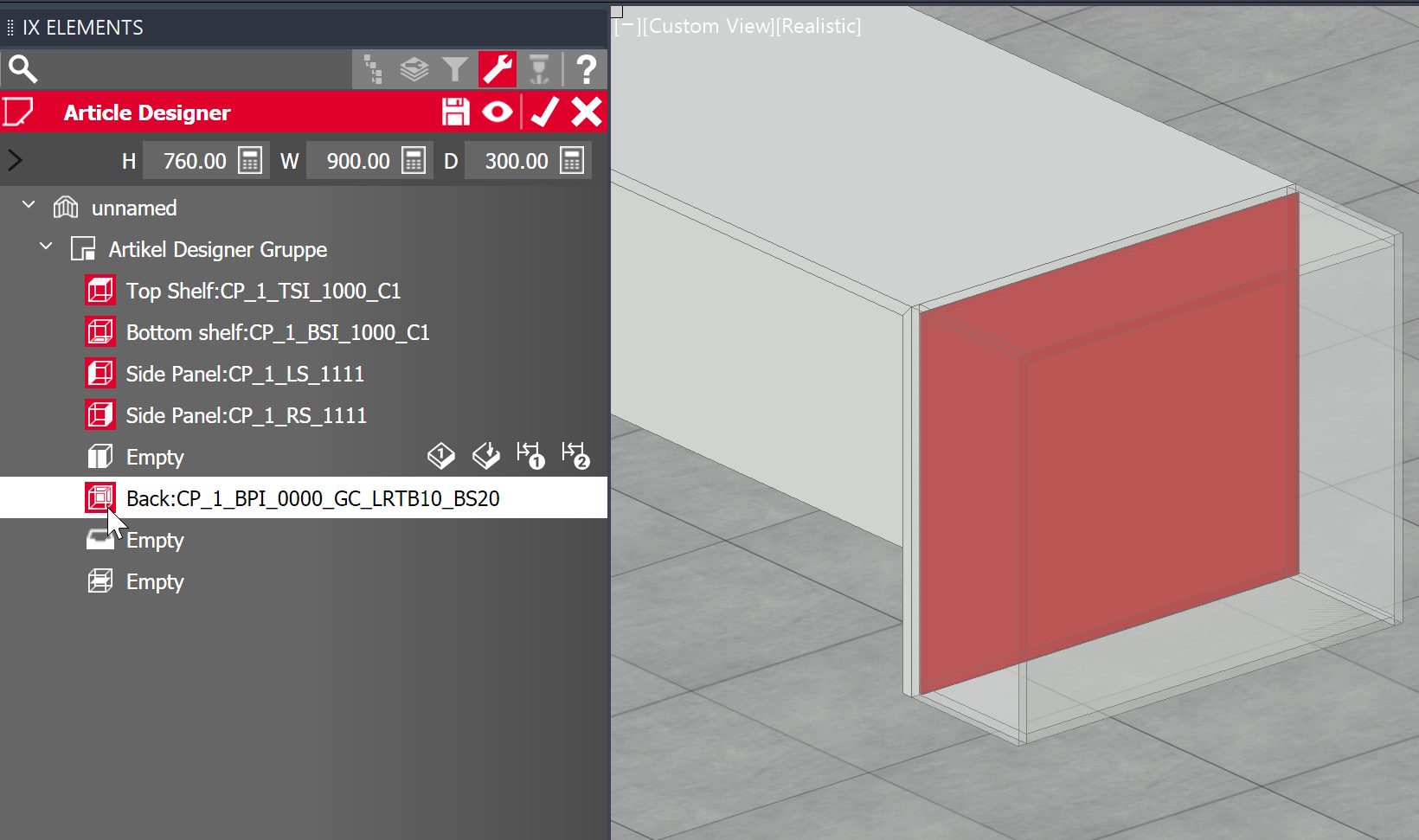
To change an element’s properties, select the element either in the tree or directly in CAD.
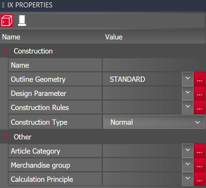
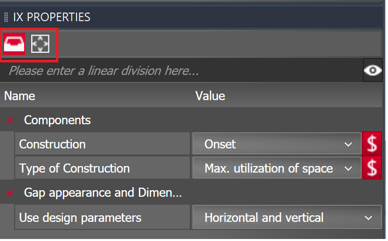
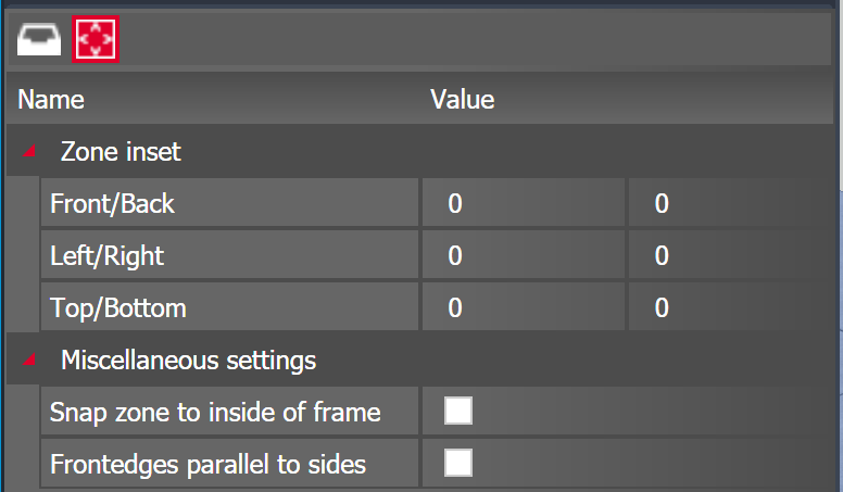
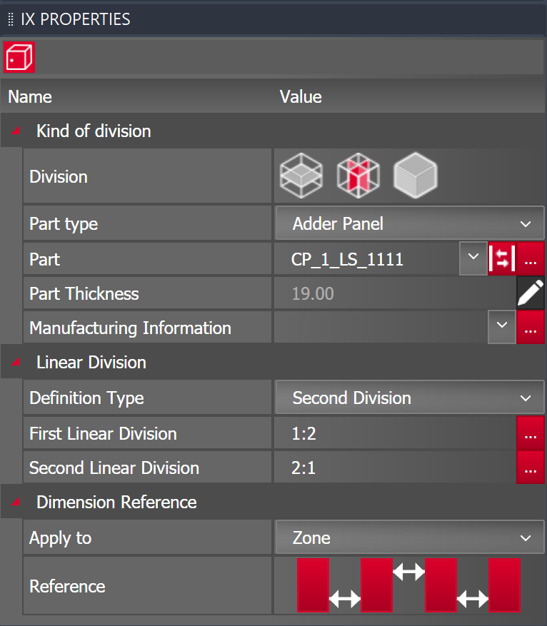
Parameters for the selected element are changed in iX Properties.
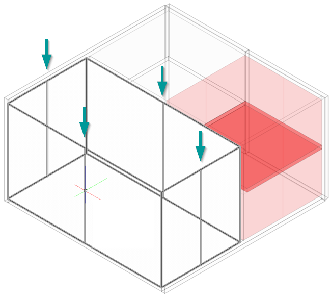
To select a zone in the drawing area, move the cursor to a vertical center line of a zone side. As soon as the preview highlights the zone, select it with a left-click.
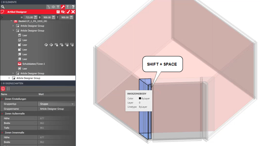
Tip: Cycle through elements and zones that overlap by using the key shortcut SHIFT+SPACE. This allows you to select elements and zones that are completely hidden. We especially recommend using the key shortcut when the realistic visual mode is active but it can also be used with the 2D wireframe mode.
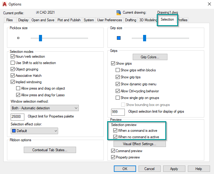
Note: Make sure, the Selection Preview options in AutoCAD Options>Selection are enabled, if the element highlighting does not work.
Activate/deactivate elements A part is activated or deactivated by left clicking on the button to the left of a tree element.
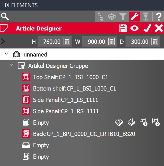
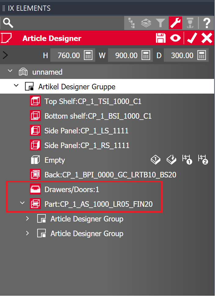
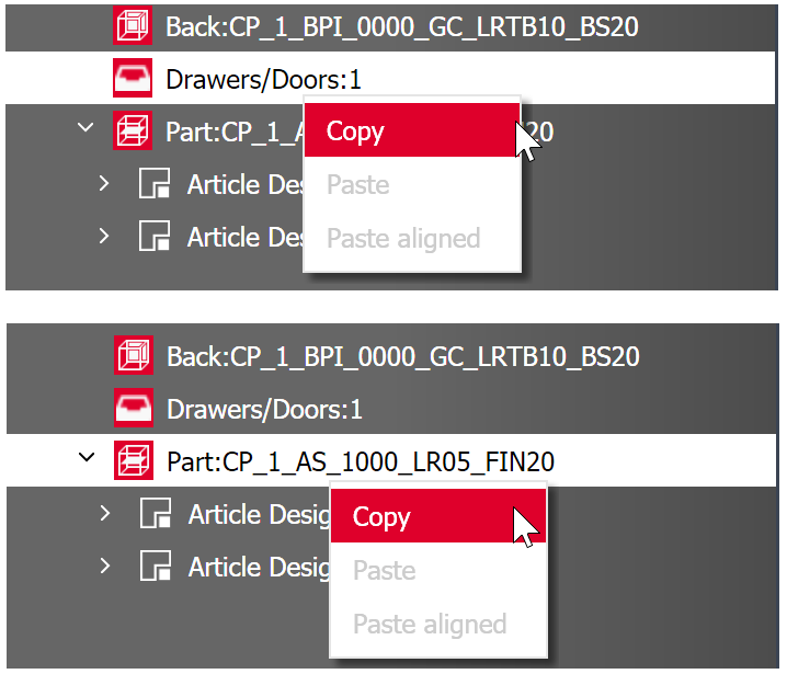
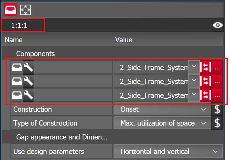
The components (drawers/doors) and division options are individual element nodes in the tree and can be separately adjusted and copied.
An Article Designer is saved/overwritten in the Article Center (main data) via the “Save” button. A new Save Article dialog will open.
Click Apply or Discard to exit the Article Designer Parametrics once more.
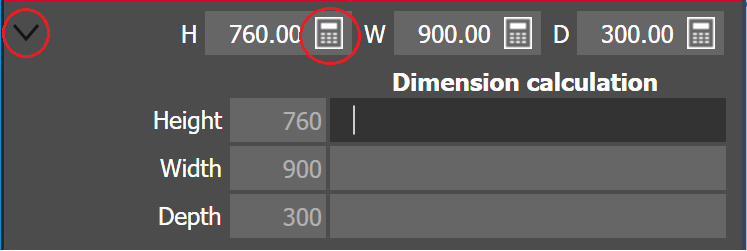
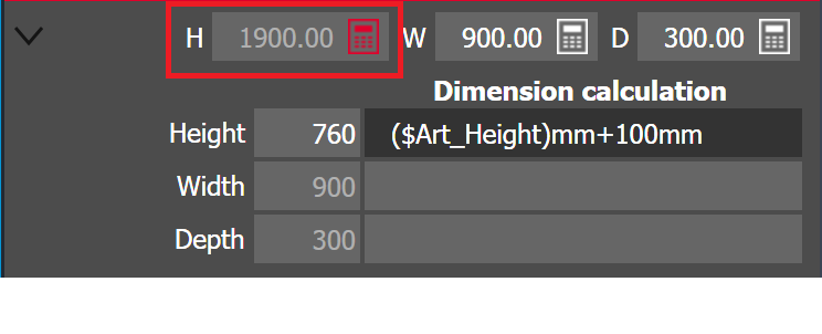
Control elements were also part of the redesign. They have been standardized and simplified. Here is an overview: Article dimensions
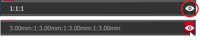
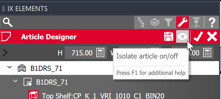
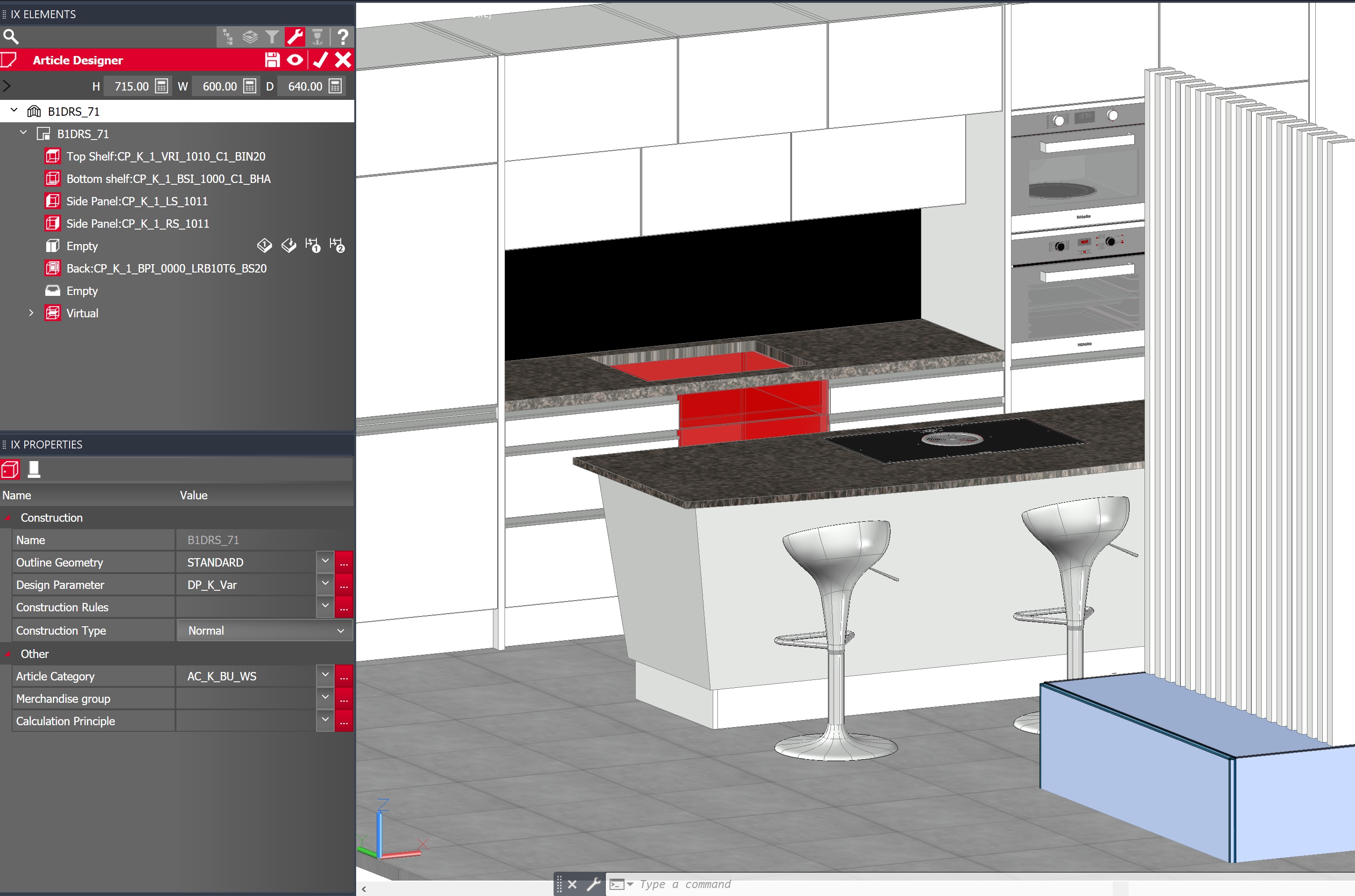
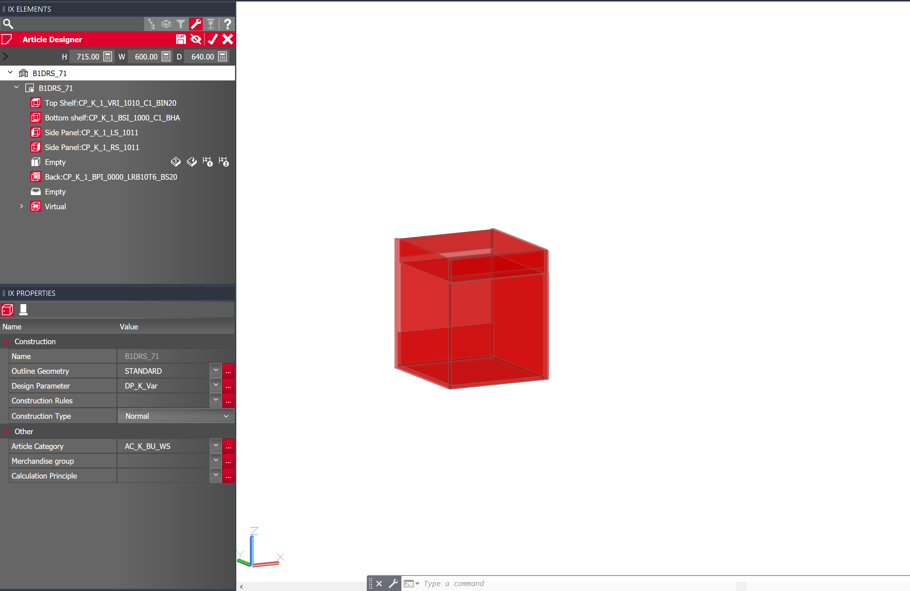
New functions New functions were added to the Article Designer along with its redesign and integration into CAD. Maintain overview in CAD – isolate the articleAs already discussed, integrating the Article Designer into CAD has made it possible to create and modify articles in the layout. This speeds up and smooths out the workflow. The user does not have to close the order and can interact with the environment (for example by taking measurements). However, there are situations in which it makes sense to only focus on one article. There is an option to do this in the red title bar, with the toggle button “Isolate article on/off” (eye), which isolates the active article and hides the rest of the layout. Clicking on the button once more displays the other articles again.
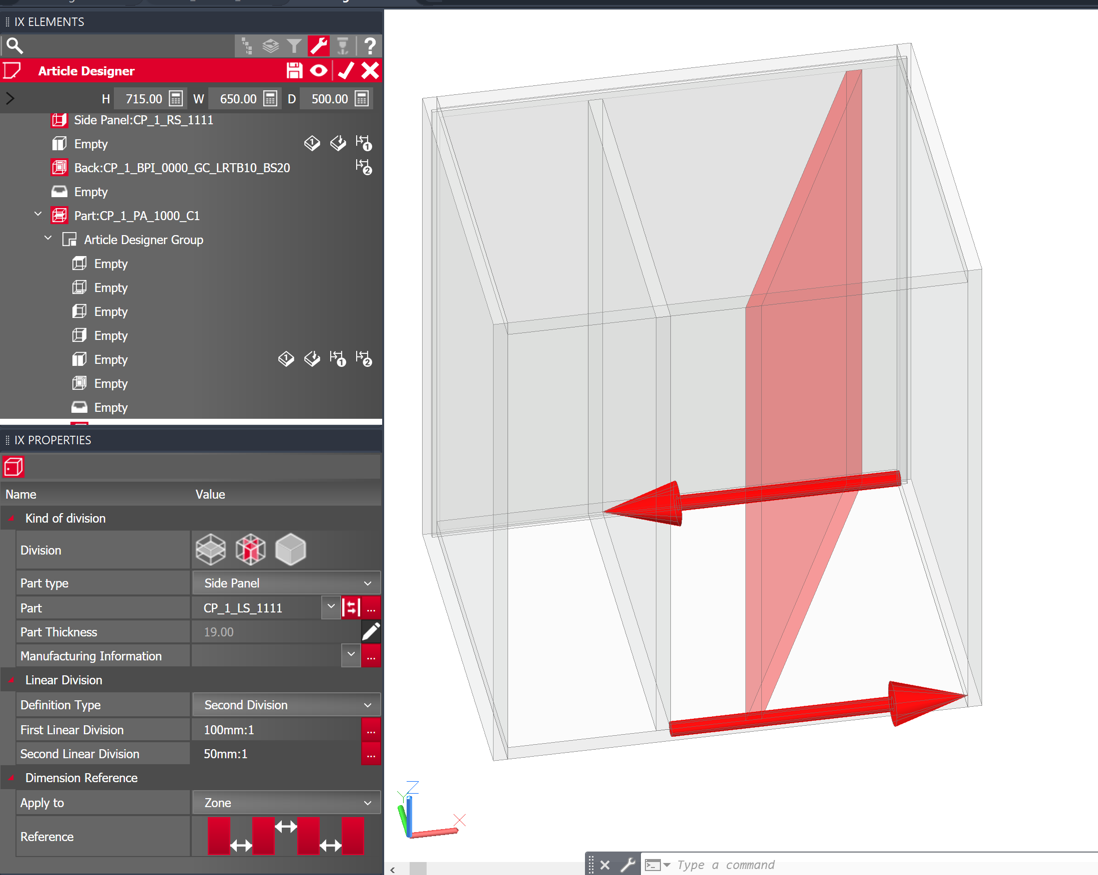
Integrating the Article Designer into CAD allows for improved visual support when changing settings. For example, arrows cover the actual length of a zone and are easier to see.
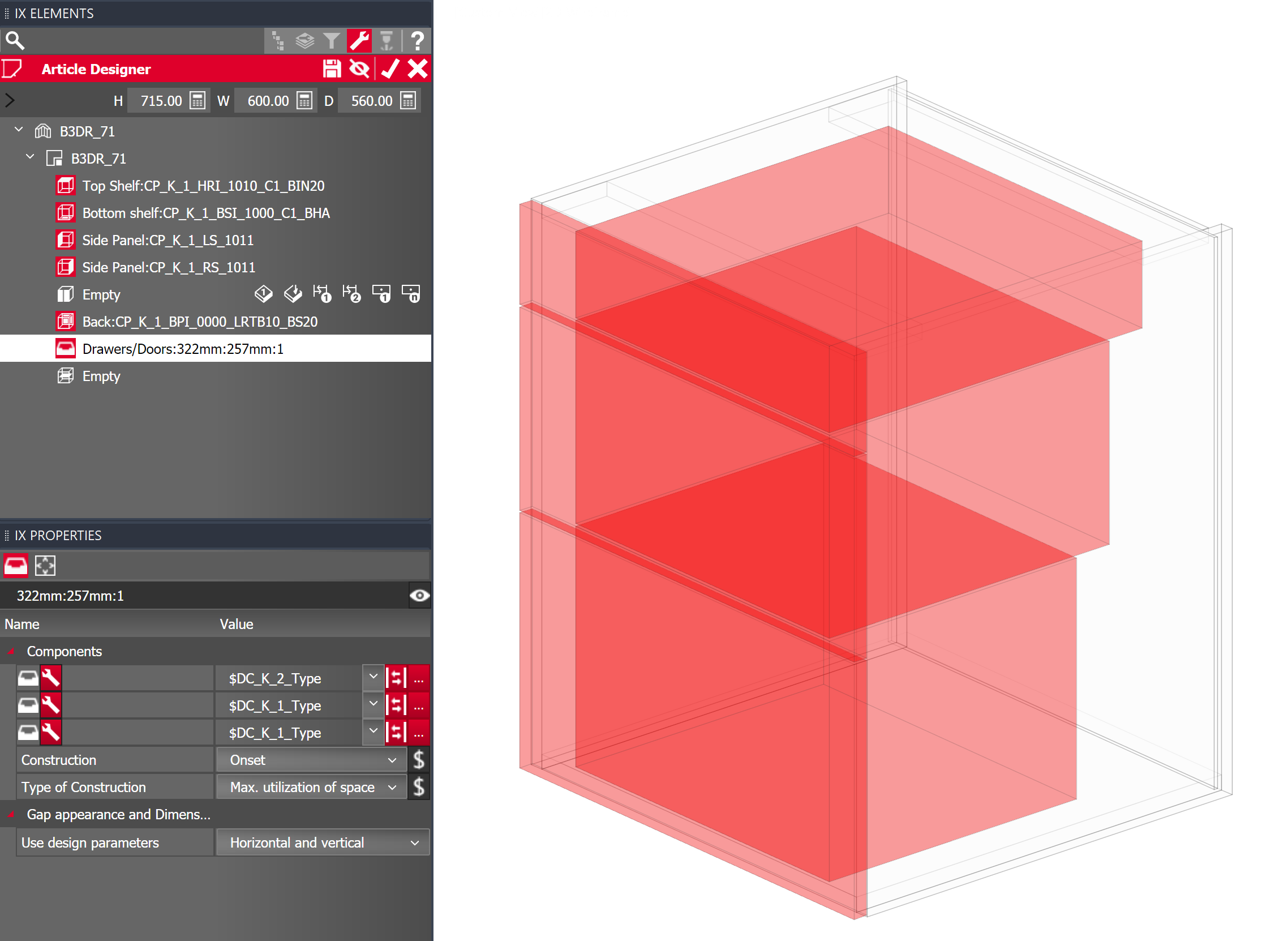
In addition, drawer zone reveals and individual drawers are displayed in CAD, making the use of space quite clear.
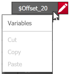
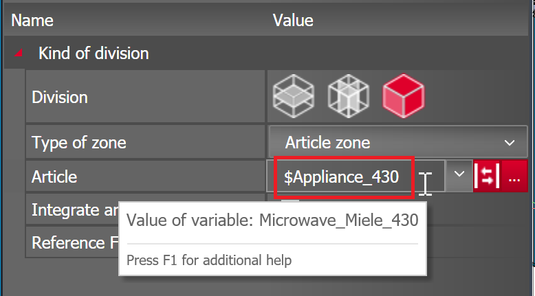
Another new function displays the current value of a variable. No extra function needs to be called for this. It is enough to hover the mouse over the variable. The assigned variable value will then be shown in the tooltip.
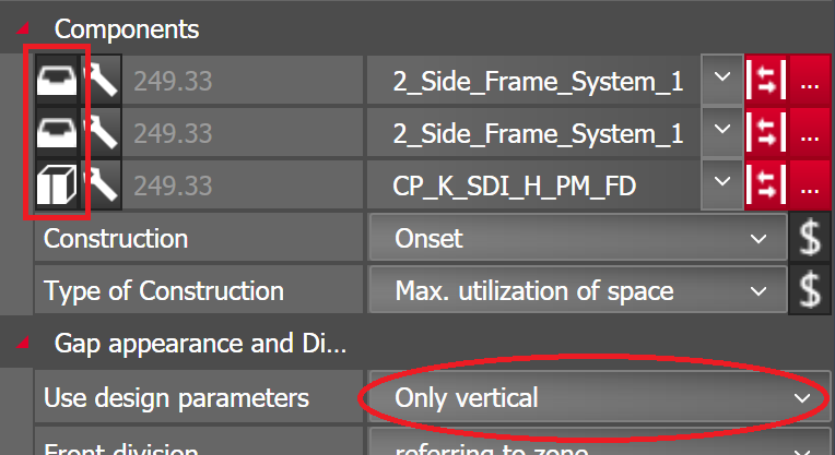
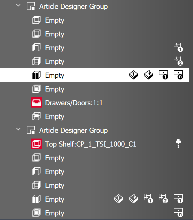
Symbols in the tree show the properties set for each zone (e.g. 1. division element). This allows the user to see, at a glance, which properties are set for which elements, without having to select the node and view the properties. The settings include:
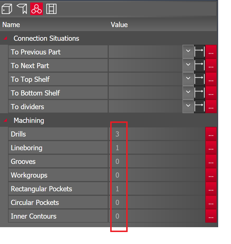
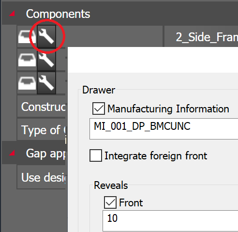
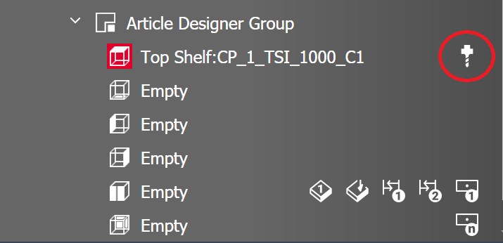
Elements to which a connection situation or machining has been assigned also have a relevant symbol next to them in the tree.
|
||||||||||||||||||||||||||||||||||||||||||||||||||||||||||||||||||||||||||||||||