
iX CAM Nesting*
*Not part of the base installation.
During nesting, individual parts of the same material are nested in a waste-optimized manner in a cutting pattern part. In iX 2023, the iX CAM Nesting module is optionally available for this purpose. It is compatible with all imos post-processors.
Note: iX CAM Nesting replaces the discontinued Direct Nest module. If you are an existing customer and use Direct Nest, please contact imos sales.
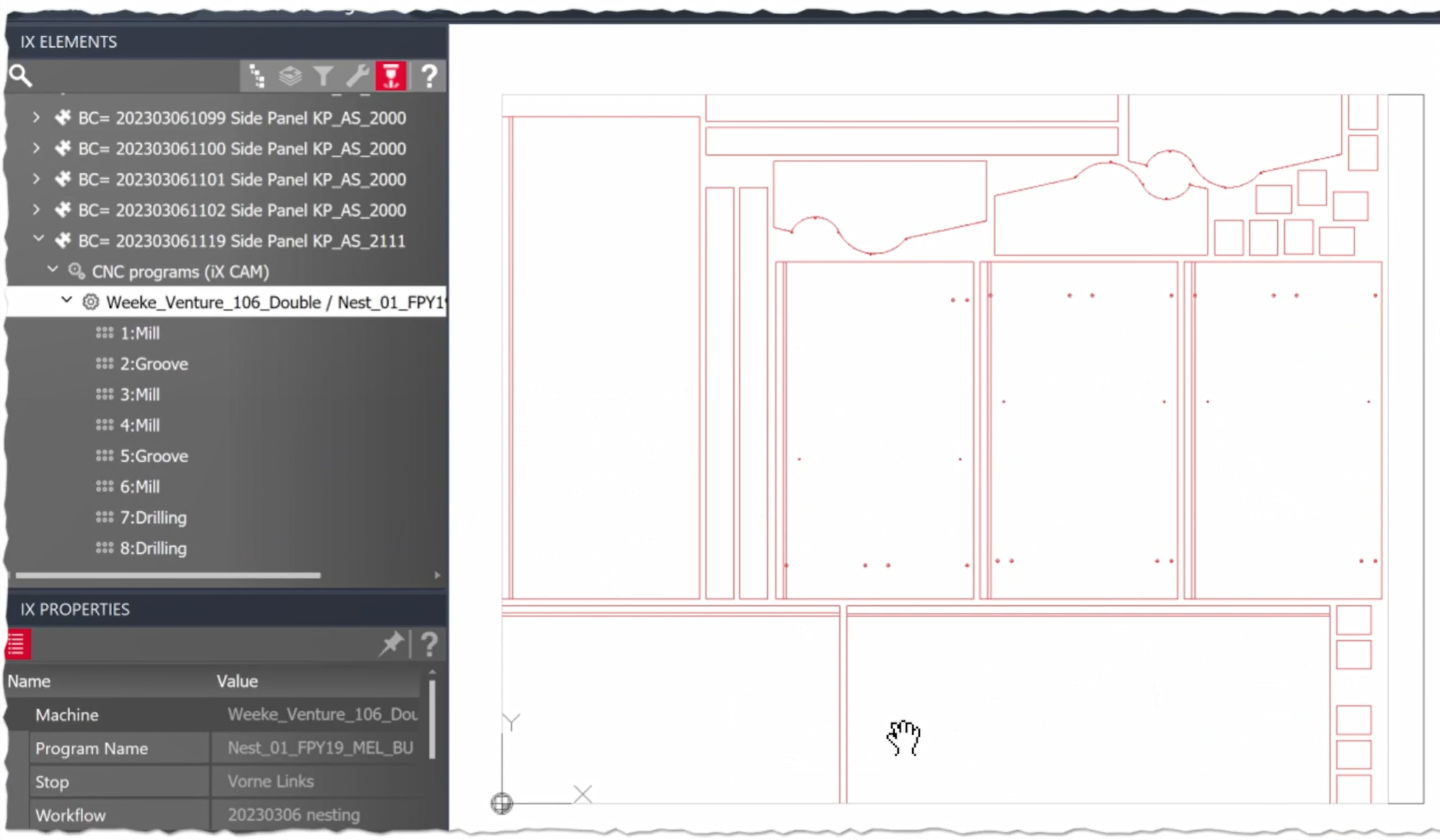
On the left in the picture: Parts, machining, programs, and tools of the nesting panel are also listed in the iXplorer tab iX CAM Edit and can be selected/edited. On the right side of the picture: Nesting panel in the drawing area.
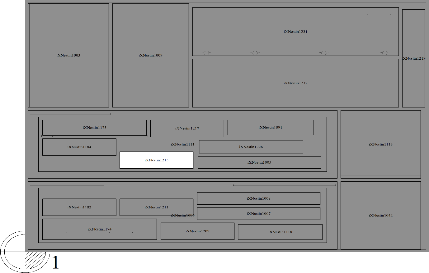
The configuration is carried out centrally in the Workflow, Machine, and Machining principles. In addition to rules for the arrangement on the nesting panel, you can also define the labeling and the type of highlighting on the part images so that a part is easy to identify in the set.
Example: A nesting plan with labeled parts and "white on gray background" highlighting. The example also shows the possibility of using cutouts within large parts to arrange small parts in them and thus make full use of the surface area.
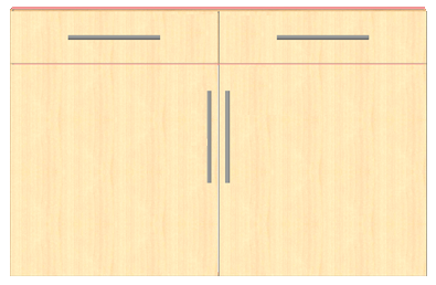
Another special feature is the arrangement of front parts as a group, so that they result in a seamless grain pattern.
Example of drawers and door fronts to be arranged as a group:
|
Nesting result when Group front parts is active in the Machining principle: 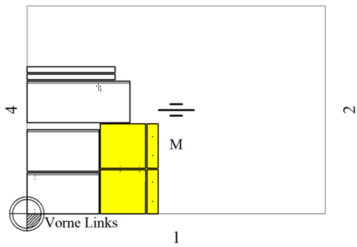 |
Nesting result when Group front parts is inactive in the Machining principle: 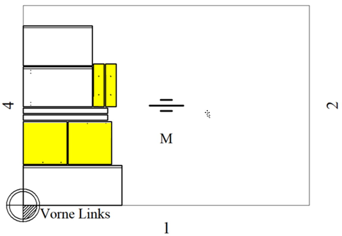 |
For more information, read the following chapters on configuration.
As soon as you start a CAM run, the nesting outputs are generated. The resulting nesting layout can be individually adjusted in iX CAM Edit (in CAD) before you create the CNC programs for production.
Note: When generating CNC data, the progress bar will temporarily halt while the nesting core is calculating possible solutions, e.g., 60 seconds. This is not a program crash/freeze. See Options in Machine Principle regarding the option "Timeout of the calculation in seconds".
During nesting, the parts are divided according to the following properties:
- Workflow
- Machine
- Material
The first program is used for each Workflow/ each Machine/ each Part with at least one nesting milling.
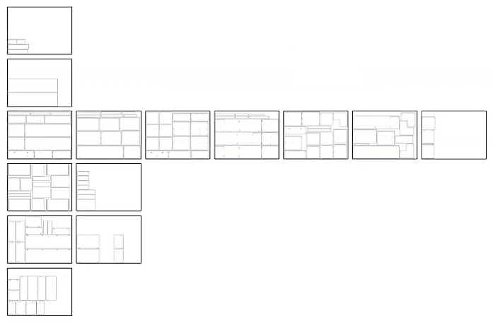
In the drawing, the nesting panels are sorted along the Y-axis by material - from bottom to top. The individual panels of a material are displayed along the X-axis from left to right. Each panel contains nested parts.
Make subsequent changes to the layout of nesting parts
You can subsequently change the layout of parts in nesting panels, for example, if you want to obtain a panel format that is better suited for future cuts.
Prerequisite:
- The order contains nesting parts.
- In the Visu Manager, the checkbox 'Show cutting parts' is checked.
Procedure:
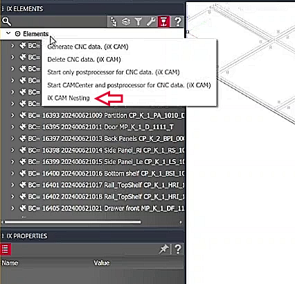
- Go to 'iX Elements' palette > 'CAM Edit' tab.
- Right-click on the root node and select 'iX CAM Nesting'. The 'iX CAM Nesting' mode becomes active. The 'iX CAM Nesting' mode does the following:
- The elements palette lists only the nesting panels and the parts in the panels.
- The drawing area provides functions for moving and aligning parts in nesting panels.
- Select a part in a nesting panel.
- Select a base point on the part. The part is now attached to the mouse pointer.
- You can either move the part within the nesting panel using AutoCAD commands like _MOVE to enter specific dimensions, or use one of the following command line functions:
- 'Rotate': Rotate the part in the nesting panel.
- Click 'Rotate' in the command line or press 'R'. The rotation points of the part are displayed.
- Select a rotation point.
- Enter an angle in the dynamic input and press 'ENTER'. Alternatively, you can rotate the part by moving the mouse pointer and confirm with a left click.
- 'Move to another nesting panel': Move a part to another nesting panel.
- Click 'Move to another nesting panel' in the command line or press 'I'.
- Select the nesting panel to which you want to move the part. The part will be removed from the original nesting panel and inserted into the other panel.
- 'Select base point': Select a base point.
- Click 'Select base point' in the command line or press 'B'.
- Select a base point on the part. Continue.
- 'Rotate': Rotate the part in the nesting panel.
IMPORTANT: As with any other change in CAM Edit, CNC data must be regenerated after moving parts in nesting panels. Otherwise, the changes will be lost when the order is reloaded. Use the 'Generate CNC Data' function in the CAM Edit context menu for this purpose. Do NOT use the 'Generate CNC Data' checkbox in the order dialog.
Configure nesting layout
You define the rules for arranging parts in the nesting part in the principles Machine and Machining of the type Mill/ Nesting contour.
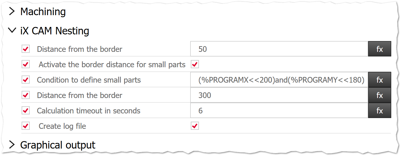
Options in Machine principle > section iX CAM Nesting
| Option | Description |
|---|---|
| Border distance | Define the distance to the border (edge) of the nesting panel. |
| Enable border distance for small parts |
If switched on, you can define a different border distance for small parts. Displays more options. Default: Off |
| Condition to define small parts | Formulate a condition that defines which parts are to be interpreted as “small”. |
| Border distance (small parts) | Define the distance between small parts and the border (edge) of the nesting panel. |
| Timeout of the calculation in seconds |
The nesting core applies a sorting algorithm to find the part layout with the least space consumption. The total duration of the sorting depends on the number and complexity of the parts. With the timeout, you decide after how many seconds the sorting should be stopped. The longer the algorithm sorts, the better the result becomes. Default: 30 |
| Create a log file | When enabled, log files are generated for support requests.
Note: To not occupy memory unnecessarily, you should clear the checkbox when you no longer need logging. Empty the log folder if it is full. Note: The option is independent of the "Create imos support file" function. This means iX Scout files are not part of a standard support file. |
Options in Machining principle of the type Mill/ Nesting contour > section iX CAM Nesting
| Option | Description |
|---|---|
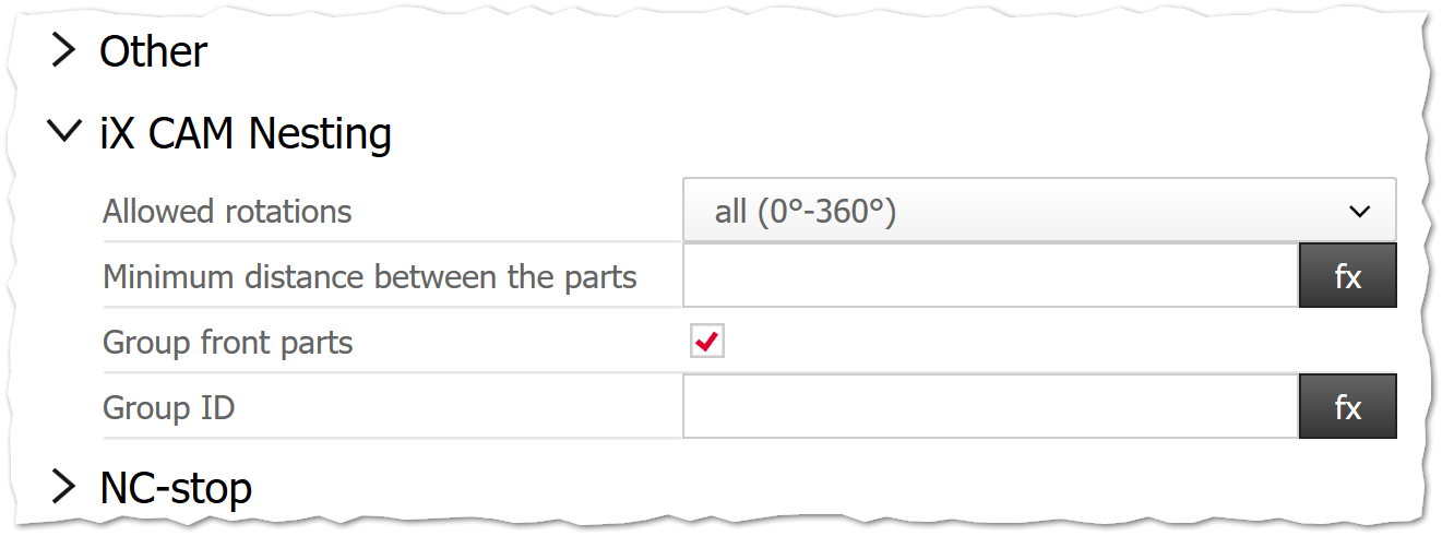
| Allowed rotations |
Control whether parts in the nesting panel can be rotated and, if so, by what angles.
Note: Nesting takes into account the grain direction of the nesting panel. An error is returned if you rotate part contours on the nesting panel and conflict with the grain direction. |
| Minimum distance between parts |
Define the minimum distance between parts on the nesting panel. Default: largest tool width Example: %TOOLDIAMETER*1.5 |
| Group front parts |
When switched on, front parts (doors, drawer fronts) are treated as a single part or as a group during nesting, so that they result in a seamless grain pattern. Within the group, the parts are offset from each other according to the tool width. The air gaps between the parts are ignored. Prerequisite: For grouping, the following properties must match:
Example of drawer and door fronts: 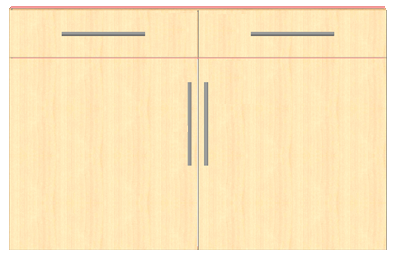 Nesting result when Group front parts is active in the Machining principle: Nesting result when Group front parts is inactive in the Machining principle: |
| Group ID |
Visible when Group front parts is turned on. Define a group-ID if you only want to group certain front parts of an article. For example, if you select the variable %IDENTINFO4 as the group-ID, the front parts that have the same value in the IdentInfo 4 field will be grouped during nesting. |
Configure nesting part images and labeling
You define the rules for creating nesting part images and for labeling in the Machining principle of the type Function/ Part image.
Options in a Machining principle of the type Function/Part image > section iX CAM Nesting
| Option | Description |
|---|---|
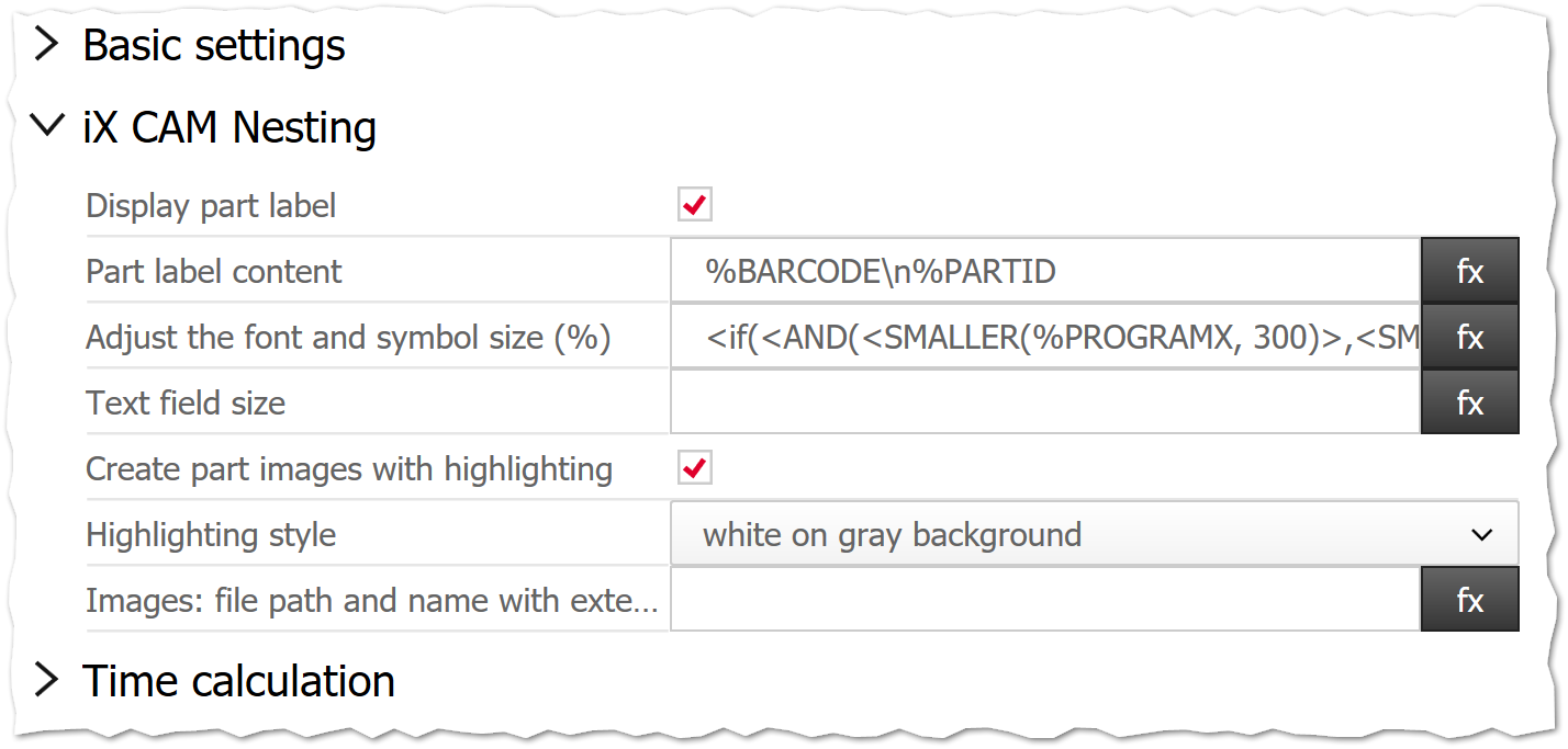
| Display part label |
When switched on, a part label is displayed in the center of the part. Default: Off |
| Part label content |
Define the contents of the part label. Example: %BARCODE\n%PARTID |
| Adjust the font and symbol size |
Define the font size. Example: <if(<AND(<SMALLER(%PROGRAMX,300)>, <SMALLER(%PROGRAMY,300)>)>,10,20)> |
| Text field size | Define the text field (box) size. |
| Create part images with highlighting |
When switched on, part images are generated in which the position of the respective part in the nesting plan is highlighted. Default: Off |
| Highlighting style |
Define a style with which you want to highlight the part in the nesting plan - either in color or with a different contour style.
|
| Image file path incl. file name and extension |
Define the path under which the file should be saved and under which file name (including file format). Example: D:\IMG\%ORDERNAME\%BARCODE.png |
Maximum available number of a core material
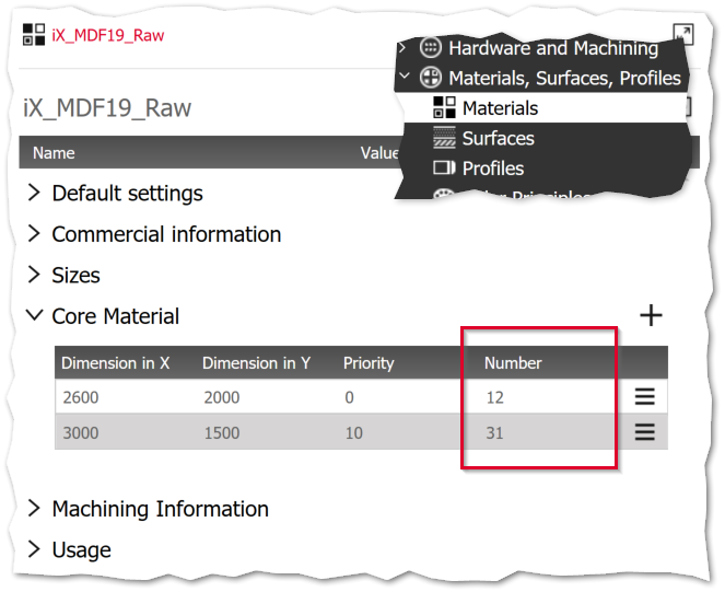
To ensure that no more panels of a certain size are used when generating nesting parts than are theoretically in stock, you can specify the maximum number of panels in the Material principle. For this purpose, the Number column has been added to the Core Material section.
iX CAM Nesting takes into account the number to decide how many high-priority core material panels to cut before switching to the next lower priority core material.
Combination with the Production Manager
With the help of the Production Manager, parts from several orders can be nested collectively. Create an output batch specifically for nesting parts and apply it to your part selection in the Production Manager.
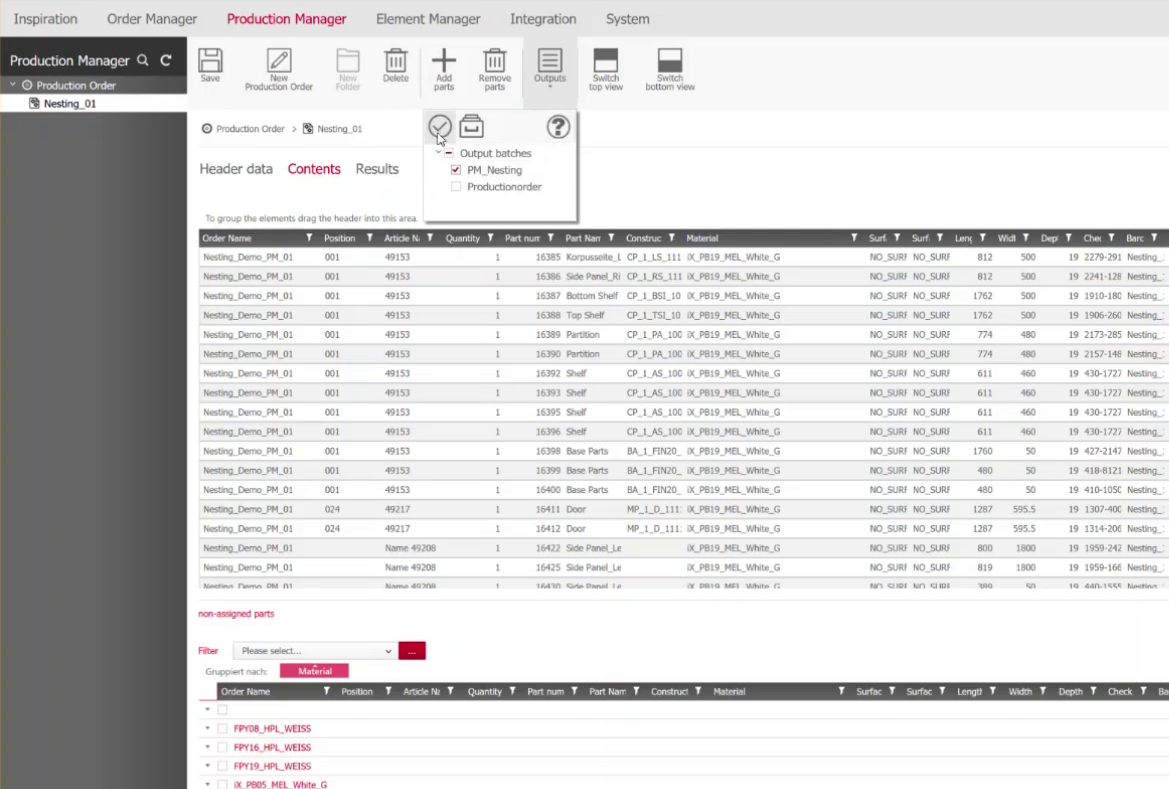
Tip: Since the assignment of parts to nesting panels is based on the material, it is advisable to group the part list in the Production Manager by 'Material'.
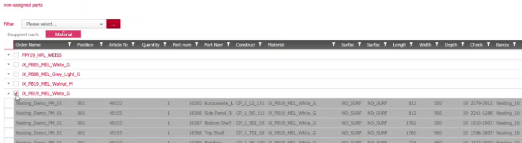
Note: Generated nesting panels cannot be modified afterward because there is neither the CAD preview nor the CAM Edit functions in the Production Manager area.